A household power source wall or desktop electro-mechanical clock-alarm clocks with familiar to us dial dial is usually plated element 343. However, in the house of such a clock may be several, so of course, a recurring problem is the replacement of time-expired batteries. In such cases, a galvanic cell can be replaced AC power supply, as described repeatedly. But here arises another annoyance - stop "progress" hours when the power outage.
More reliable and convenient in operation are AC drives power supply in the form of small Nickel-cadmium batteries D-0.1 D-0.125. They will provide normal work hours after both short-and long-term outage voltage.

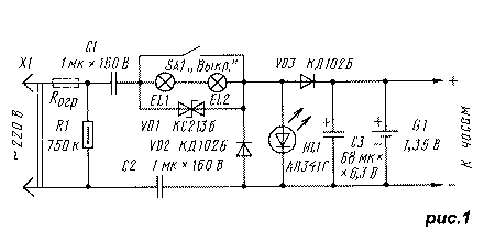
The proposed power supply electro-mechanical hours, the diagram of which is shown in Fig.1, is an advanced option blocks described in [3,4]. The main difference is the possibility of illumination of the dial in the dark days. The design of the unit corresponds to the dimensions of the electrochemical cell 343 (R14), allowing you to quickly embed it in your watch without any improvements.
Capacitors C1 and C2 function as ballast reactive elements, absorbing excess voltage. Their nominal capacity determine the value of the current flowing through them. Due to the capacitors included in the different network wire, the voltage on all other elements of the block relative to the ground is less than half the network. In addition, in the case of an emergency these elements will be connected to the ground fault current will be limited and will not lead to heavy consequences.
If the switch contacts are closed SA1, when negative half-wave of the mains voltage at the top (the scheme) the wire diode VD2 is opened and through it will charge the capacitors C1 and C2. When the positive half the capacitors become charged, the current will flow, first of all, through open diode VD3 and will begin to recharge the battery G1 and capacitor C3. The voltage of a fully charged battery will not less than 1.35, and the HL1 led is about 2V. Therefore, the led will to open and thereby limit the charging current of the battery. Consequently, the battery will always be charged.

Thus, in the presence of voltage clock feed from it during the positive half-cycles, and during the negative half cycle of the energy stored by the battery G1 and capacitor C3. When mains voltage power source becomes only the battery, the energy which will last for a few days and even weeks of continuous work hours - depending on the values the consumed current.
The lighting of the dial include opening contacts of the switch SA1. In this case, the charging current and discharging capacitors C1 and C2 flows through the filament of lamp EL1 and EL2, and they begin to glow. As previously confined two-anode Zener diode VD1 now performs two functions: it limits the voltage across the lamps to the value at they glow with a small nedoklan (which increases their lifespan), in the case of burning out of the filament of one of the lamps, pass through charge-discharge current of the capacitors, which prevents a malfunction in the the PSU in General.
Resistor R1 is used to discharge the capacitors C1 and C2 when the device is disconnected from the network.
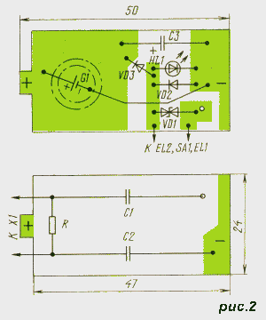
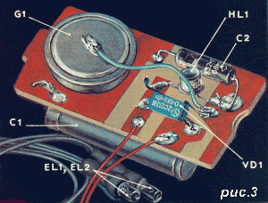
All elements except incandescent lamps EL1, EL2 and the switch SA1 is placed on the PCB of bilateral foiled fiberglass thickness 1.5...2 mm (Fig.2). Form Board details it resembles a galvanic element 343 (Fig.3), which can insert in the appropriate compartment of hours. To simulate contacts plus and negative electrodes of the battery, the traces of both sides card edge opaânnymi thin foil (for Example, remote from the workpiece cost). On the Board are glued capacitors C1 and C2, the battery, and then raspalaut other details of the power supply.

Capacitors C1 and C2 - K73 rated the voltage of at least 300V, C3 - K52, K50-6. Two-anode Zener diode XB (VD1) can be replaced by two counter-consistently Zener DD, XI, XA. Diodes VD2 and VD3 - rectifying any small-sized. Led HL1 - any of a series of AL, it is only necessary pre-selecting an instance, which has a forward voltage at a current of 10 mA will be 1.9 2.1...V. incandescent Lamp EL1 and EL2 - SMN,3-20 ( the voltage of 6.3 V and a current intensity of 20 mA) or similar low voltage. The switch SA1 may be of any design, it is only important to his body was reliably isolated from the network.
In one of the input conductors of the device, for example, the inside of the fork X1, it is desirable to include current limiting resistor Rогр (in Fig.1 are denoted by dashed lines) resistance 36...51 Ohms power dissipation 0.5 W, to prevent possible failure of components of the device at the time connect the power adapter to the network.
Mounted the power supply can be placed in a cylindrical body of insulating material or just wrap it insulation tape. Incandescent and compact switch SA1 set in the most appropriate place for the watchcase.
Literature
Publication: N. Bolshakov, rf.atnn.ru


