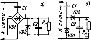
AC adapter with damping capacitor (Fig. 1), in fact, there is a voltage divider, whose upper shoulder - capacitor, and the bottom is a complex non-linear diode-resistance-capacitor circuit. This defined and disadvantages (and advantages, of course) of such devices.

Fig.1
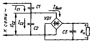
In order for a source to work in a wide range of load current with high efficiency, sufficient input voltage divider to perform purely reactive, for example, a condenser (Fig. 2). It additionally helps to stabilize the output voltage source with series compensation or switched-mode regulator, what not to do in a usual source with damping capacitor. As shown in the article by S. Biryukov, "calculation of the utility power source capacitor with damping" - "Radio", 1997, No. 5, p. 48-50, - series regulator can be used only by limiting the voltage at its input, which again significantly reduces efficiency.

Fig.2
Source with capacitor voltage divider should be used for joint work with pulse stabilizers. Perfect it for your device, long consuming low current, but requires at some point a sharp increase. Example - apartment watchdog on chips "MNPT with the Executive relay node and sound alarm.
The current consumed capacitor divider, will have a phase shift of 90 degrees. respect to the supply voltage, so a voltage divider on the reactive elements do not require refrigeration. Based on the foregoing, the current through the divider like, you can choose an arbitrarily large. However, the unjustified increase in the current divider will lead to an active losses in the wires and increase the mass and volume of the device. Therefore, it is advisable to take the current through the voltage divider within 0.5...3 of the maximum load current.
The calculation of the source with a capacitive divider is simple. As follows from the formula (2) mentioned in the article, the output voltage Uвых and full output current (Zener diode and load IOUT) source on figure 1,and are connected as follows:
IOUT = 4fC1(2Uc-Uвых).
This formula is used for calculation of the source with capacitor divider, it is just necessary to replace C1 on the total capacitance of a parallel-connected capacitors C1 and C2, shown in Fig. 2. a Uc - Uc2x (the voltage at the capacitor C2 at RH = °°), i.e. Uc2x = = Uc-C1/(C1+C2). Then VIH = 4f(C1+C2)x x[Uc-C1-i/2/(C1+C2)-Unbix] or after obvious transformations VIH = 4f-C1 [Uc^2 --iwih(1+C2/C1)].
Since the voltage drop across the diodes of the bridge arc voltage with small values of Kwih becomes noticeable finally get VIH = 4f-C1 [Uc^/2- (Cvih + ZD) (1 + +C2/C1)].
From the formula it is seen that at PH=0 (i.e. when Uвых=0) current IOUT, if we neglect the voltage drop across the diodes, remains the same as at the source of supply, assembled according to the scheme 1 ,and. The voltage on the output with no load decreases: Uauxx = =Uc-C1^/2/(C1+C2)-2Un.
Capacitance and working voltage of the capacitor C2 can be chosen according to the required output voltage is the ratio of the capacitance values of C1/C2 is inversely proportional to the values falling on C1 and C2 voltage. For example, if S1 =1 µf and C2=4 μf, the voltage Uc1 is equal to 4/5 of the mains voltage, a Uc2=Uc/5 that when the voltage Uc = 220 corresponds To 186 and 44 V. it Must be considered that the amplitude of the voltage is almost 1.5 times higher than the existing, and to select the capacitors corresponding to the rated voltage.
Although theoretically capacitors in AC circuits do not consume power, in reality they are due to the presence of losses can be allocated a certain amount of heat. Check in advance the suitability of a capacitor for use in the source by simply connecting it to the mains and estimating the temperature of the hull in half an hour. If the capacitor C1 has time to warm up noticeably, it should be considered unsuitable for use in the source.
Virtually no heat special capacitors for industrial electrical installations - they are designed for a large reactive power. These capacitors are used in fluorescent lamps, electronic control devices, induction motors, etc.

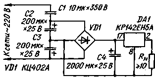
Fig.3
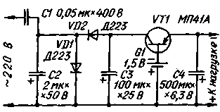
Below are two practical schemes power supplies with capacitor divider: patibility General purpose (Fig. 3) on the load current up to 0.3 A and uninterruptible power supply for kartsovnik electro-mechanical hours (Fig. 4).

Fig.4
A voltage divider pyativolnovye source consists of a paper capacitor C1 and two oxide C2 and C3 forming the bottom under the scheme nonpolar shoulder capacitance of 100 μf. Polarizing diodes oxide pairs are left in the circuit the diodes of the bridge. For component values indicated in the diagram, fault current (RL=0) is equal to 600 mA, the voltage across the capacitor C4 in the absence of load - 27 V.
Electro-mechanical watches usually feed from one galvanic cell voltage of 1.5 V. the Proposed source produces a voltage of 1.4 V At average load current of 1 mA. The voltage taken from the divider SS, straightens node the elements VD1, VD2, C3. No load voltage on the capacitor C3 does not exceed 12V.
Author: O. Haviko, Moscow; Publication: N. Bolshakov, rf.atnn.ru


