To power many portable consumer devices or repair of radio equipment convenient to have a universal stationary source stabilized DC voltage. Usually this source is quite adjustable output voltage from 1,5...30 V maximum load current up to 1 A.
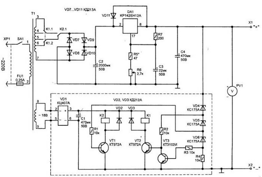
Such a source can easily be performed on the integrated circuit from CEA (B), Fig. 4.6. Its circuit diagram is typical and in particular does not need any explanations.

Fig. 4.6. The electrical circuit of the power source (click to enlarge)
The chip inside is protected against overcurrent and can dissipate on radiator power up to 10 watts.
In the manufacture of a universal power supply with adjustable output voltage in a wide range to provide for power transistor Lite mode, often used mains transformer with a partitioned the secondary winding. In this case, the transformer taps are connected manually using the switch, depending on the level of the output voltage so that the difference between input and output was not very large. Instead of the switch this task may perform automatic the device shown in the figure by dotted lines.
To switch the four taps of the secondary winding of the transformer T1 is enough only two relay having two groups of switching contacts.
Relays are activated in sequence. The diagram shows the original the position of the contacts K1 and K2, when none of them included.
The switch has three switching threshold and the operation of relay is as follows:
1) once the output voltage exceeds 7.5 - turn on relay K1;
2) when exceeding level 15 In signal relay K2;
3) when the level is exceeded 22.5 - off K1.
The voltage taken from the secondary winding of the transformer T1 will be speed increase.
The level switching threshold is determined by the operating voltage applied Zener (VD4.VD6). In this embodiment, the circuits for the Zener he KSA is 7.5 V. This allows the output power to change the voltage from 1.5 to 30 In only one regulator (R6).
The scheme eliminates the chattering of the relay contacts when switching and with proper installation of the switch it does not require any adjustment.
In the device used details: variable resistor R6 type SPZ-4A, other resistors MLT or C2-23. Polar capacitor C3 is better to use tantalum, for example type K52-1B, K53-4A; C1, C2 and C4 can be of any type.
Transistors VT1, VT2 should be with high gain and can replace CT (A. D).
Relays K1, K2 are applied to operating voltage 24...27 V and should have two the group of switching contacts, allowing switching current up to 1...2 A.
For example, such are the RPG-8-2602 24 V, RES, RS4.520.203, RES RF4.500.407 and some others.
Mains transformer T1 can be used from the uniform. TP-220-50, TP-220-50, TP-220-50. It is not difficult to make a network the transformer on the basis of any existing transformer iron.
Chip DA1 is mounted on the radiator. The radiator should not have electrical contact with the hull design, as DA1 pin 8 is connected with the fastening element of the chip.
Author: I. P. Shelestov


