The use of capacitors to reduce the voltage supplied to the load from the lighting network, has a long history. 50 years of ham radio operators used in a wide transformerless power supplies radios capacitors, which are included in series with the filaments of tubes. This allowed us to eliminate the quenching resistor, which is a heat source and heating the entire structure. In recent times we see the return of interest to power sources with damping capacitor. Inherent to all without exception, such devices lack - increased risk due to output galvanic connection to the electrical network is clearly understood, but is allowed in the calculation of the literacy and accuracy of the user. However, these constraints are insufficient to keep out of trouble, why transformerless devices may have only a very limited application.

Here may represent a compromise version of the source that provides electrical safety, with damping capacitor and a simple, accessible novice radio Amateur transformer. This transformer will work, if the voltage on the primary winding to limit the value of about 30 V. For this quite a 600...650 turns of relatively thick, comfortable when winding wire; for the sake of simplification, it is possible for both windings to use the same wire. Over the voltage here will assume the capacitor is connected in series with the primary winding (the capacitor must be designed for a rated voltage of At least 400). On this principle it is possible to arrange the low voltage loads with a current in the primary circuit (including a small transformation ratio) up to 0.5 A.
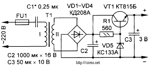
The figure shows the scheme of such a device, suitable for operation with a garland of LEDs desktop mini Christmas trees or audio player.

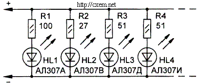
The inclusion of Svetovidov (8...10) is performed in parallel; this eliminates the usual mess of wires, they are easier to make invisible in "needles" of the trunk and branches. The transformer can be assembled on the yoke Sh. For winding suitable wire sew-1 (d=0.16 mm; number of turns of the primary and secondary windings - 600 and 120...140 respectively. To make such a transformer is not working.
Electric strength not less than 2 kV will provide an insulating spacer between the windings of the Mylar film having a thickness of 0.1 mm or condenser paper. To ensure that the device is not out of order when disconnecting the load to the output of the bridge VD1 - VD4, you should connect Zener DG. In normal mode it does not work because it has a minimum voltage stabilization above the operating output of the bridge. Fuse FU1 protects the transformer and stabilizer in the breakdown of the capacitor C1. To limit the current when the power supply is connected to the network in series with C1 it is necessary to include a resistor of a few hundred Ohms, and for discharge of the capacitor after the off - parallel to a resistor of a few hundred ohms. In the chain of series-connected capacitance (capacitor C1) and the inductive impedance (transformer T1) there may be resonance voltage. Keep this in mind when designing such power sources.
Publication: www.cxem.net


