When designing and building analog devices usually need a source supply with an output voltage of 8...25 V, load current of 0.3...0.4 A, and, besides having a small pulsation level and protected from the circuit of the output circuit.
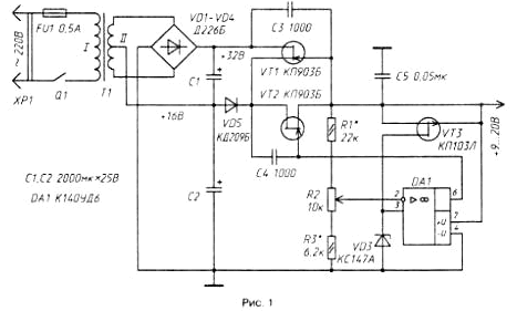
The following describes the power supply that meets these requirements. It the output impedance is approximately 5 mω, the voltage ripple is less than 1.2 mV. The device (Fig. 1) consists of a network of the transformer T1 with bridge rectifier the diodes VD1 - VD4 and compensation of the voltage regulator transistors VT1, VT2 Oh and DA1. Rectifier produces two voltage - 16 and 32 V.

At an output voltage not exceeding 12...13 In (set variable resistor R2), the regulating transistor VT2 falls 2...4 V. For the transistor VT1 is voltage closing, so the current through it is small and basic load current flowing through the diode VD5, E. a stabilizer 16 is supplied with the voltage V.
If the output voltage to increase, the voltage drop across the transistor VT2 will be reduced which will lead to the opening of the transistor VT1. Now to the regulatory element of the stabilizer include both transistor VT1 and VT2 In this case, the stabilizer will be powered by a voltage through 32 In transistor VT1, diode VD5 will be closed. In other words, the transistor VT1 opens or closed depending on the voltage established at the output in the device.
Thus, the input voltage is automatically changed by the output voltage variation. The result is reduced power dissipation on the control element and increases the efficiency of the stabilizer. Furthermore, the use of field-effect transistors has allowed to simplify the task of protection from emergency overload, as the output current of the regulator circuit when the output circuit is not may exceed the initial drain current of the transistor VT2 (0,3...0,4 A). For example, if at a voltage of 20 In the output circuit will be closed, it will lead, first, to the closing of the transistor VT1 and the lower input voltage stabilizer to 16 V, and the current will be limited the above value. The transistor will dissipate power 5...6 W, and in this mode it can work for a long time.
Capacitors C3, C4 prevent the possible excitation of the stabilizer.
The device can use the OS CUD, CUD (with any letter index), COD, COD, COD, COD; the transistors. CPA, CPV (VT1, VT2),CPM,CPD (VT3), rectifier diode units. CCB - CCE [VD1-VD4), diodes CDV, CDB (VD5), Zener XA, XA, XB, KC168A VT6; Capacitors C1, C2 - C50-12, K50-6; C3, C4 - CT, KLS, km, BM; C5 - MBM, BM. Resistor R2 - SP - 1,sve-0,4, rest Wed, MLT.
Mains transformer T1 must provide for the winding II AC voltage 10...12 V at a current 0.5 A.
You can use unified transformers. TPP-127/220-50, TPP-127/220-50, TP-127/220-50 TSO-127/220-50, T-127/220-50, etc.
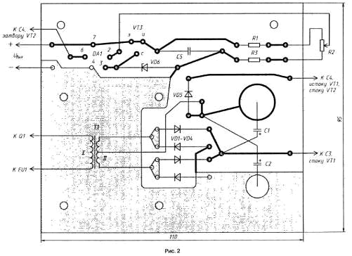
All parts except fuse FU1, switch Q1 and the variable resistor R2 is mounted on the circuit Board (Fig. 2) of foiled fiberglass with a thickness of 1.5...2 mm.

The front panel is attached to the circuit Board screws with the dural area. The rear wall of the block serves as a finned heat sink; you can apply and plate thickness 2,5...3 mm with an effective area of dispersion is not less than 100 cm2. The unit housing made of sheet aluminum having a thickness of about 0.7 mm., the Casing consists of a tray, which strengthen the Board with the front panel and the heat sink and U-shaped cover. In the pan and the lid should provide ventilation openings.
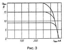
The building block is to install the limits of output voltage regulation, which choose the resistors R1 and RЗ. It is desirable to control the output characteristics of the device for different voltage values. Graphics should be of the form shown in Fig. 3.

To indicate the unit is switched on in series with the transistor VT3 (in circuit flow) you can enable the led, for example, ALB.
Author: I. Nechaev


