Any developer may face the problem of a simple and reliable the power source for the design of the device. Currently there are quite simple schematics and corresponding elemental base, allowing you to create switching power minimum the number of elements.
Your attention is invited to the description of one of the options simple network switching power supply unit. The power supply is implemented on the basis of the IC UC3842. This chip is widespread, ranging from the second half of the 90-ies. It implements many different sources power for TVs, Fax machines, VCRs and other equipment. Such the popularity of UC3842 received due to their low cost, high the reliability, simplicity of circuitry and minimal requisite binding.
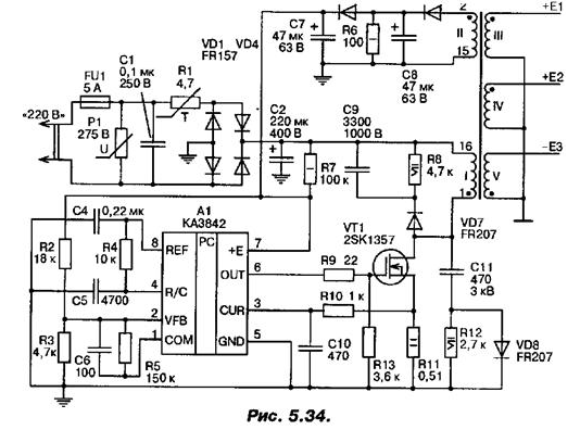
At the input of the power supply (Fig. 5.34), is a mains voltage rectifier, includes fuse FU1 at a current of 5 A, the varistor P1 275 In for protect the power supply against excessive voltage, a capacitor C1, the thermistor R1 4.7 Ohm, diode bridge VD1...VD4 diodes FR157 (2 A, 600 V) and the filter capacitor C2 (220 UF 400 V). The thermistor R1 in the cold the state has a resistance of 4.7 Ohms, and when the power is turned on, the charge current capacitor C2 is limited to this resistance. Further, the resistor heats up due to the passing current through it and its resistance drops to a tenth of an Ohm. However, he has virtually no effect on the future operation of the scheme.

Resistor R7 provides power to the IC in the start-up period power supply. Winding II transformer T1, diode VD6, capacitor C8, resistor R6 and diode VD5 form so called feedback loop (Feedback Loop), which provides power IC in operation, and which is stabilization of the output voltages. Capacitor C7 is a power supply filter IC. Elements R4, C5 are frameshadow chain for the internal pulse generator IC.
The resistive divider R2, R3 sets the voltage generated by the loop return communication, at the input of the error amplifier, in other words, determines the voltage stabilization. Elements R5, C6 required for compensation. The frequency response of the error amplifier. Resistor R9 Is a current-limiting resistor R13 protects field-effect transistor VT1 in case of breakage resistor R9. Resistor R11 is a measurement to determine the current through the transistor VT1. Elements R10, C10 integrating form a chain through which the voltage from the resistor R11, which are the equivalent of the current through the transistor VT1, supplied to the second comparator IC. Elements VD7, R8, R9, VD8, R11 and R12 form the desired pulse shape, eliminate spurious generation of fronts and protect the transistor from the powerful voltage pulses.
The transformer is wound on a ferrite core with a frame ETD39 Siemens+Matsushita. This set features a round Central core ferrite and plenty of room for thick wires. The plastic frame has the findings for the eight windings.
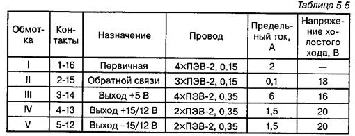
The Assembly of the transformer by means of special mounting of the springs. You should pay special attention to the thoroughness of the insulation of each layer windings with use of varnished cloth, and between windings I, II and rest of windings should lay several layers of varnished cloth, ensuring reliable isolation of the output the circuit from the network. Winding should be wound way "round", not twisting the wires. Naturally, there should be no overlap of wires neighboring turns and loops. Winding transformer data are shown in table. 5.5.

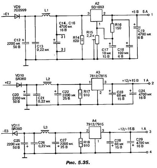
The output part of the power supply unit is presented in Fig. 5.35. She galvanically unleashed from the input part and comprises three functionally identical unit, consisting of a rectifier, LC filter and a linear regulator. The first block - stabilizer 5 In (5) is made on the IC linear regulator A2 SD1083/84 (DV, LT). This chip has a switching circuit, the housing and the parameters similar MS KREN, however, the operating current is 7.5 And for SD1083 and 5 And for SD1084.

The second block stabilizer +12/15 In (1 A) made on the IC linear stabilizer A3 7812 (12V) or 7815 (15). Domestic counterparts of these IC - KREN to appropriate letters (B, C) and CEN/15. The third block is stabilizer -12/15 In (1 A) made on the IC linear regulator. A4 7912 (12 In) or 7915 (15). Domestic counterparts of these IC - COD.
Resistors R14, R17, R18 required to absorb excess voltage at idle the go. Capacitors C12, C20, C25 selected with headroom voltage due to a possible increase in voltage at idle. It is recommended to use capacitors C17, C18, C23, s type K53-1A or K53-4A. All IC are installed individual lamellar radiators with a minimum area of 5 cm2.
Structurally, the power supply unit is designed as a one-sided printed Board installed in the housing of the power supply of the personal computer. Fan input and network connectors are used for the intended purpose. Fan connected to the stabilizer + 12/15, although it is possible to make an additional the rectifier or regulator +12V without special filtering.
All radiators are installed vertically, perpendicular to the outlet through the the fan air flow. To the outputs of the stabilizers are connected by four wire length 30...45 mm, each set of output wires is crimped special plastic clips-straps in a separate wiring and is equipped with a connector of the same type that is used in a personal computer to connect different peripheral devices. The stabilization parameters are determined by the parameters IC stabilisers. Voltage ripple is determined by the parameters of the Converter and approximately 0.05% for each stabilizer.
Author: A. P. Seman


