


")

This source can be used to power any load capacity of up to 15 to 20 watts and has a smaller size than but with step-down transformer operating at a frequency of 50 Hz.
The power source is performed according to the scheme of a single-step pulsed high-frequency transducer, Fig. 5.1. Transistor assembled oscillator operating at a frequency of 20…40 kHz (depends on settings). Frequency is adjusted capacitance C5. Elements VD5, VD6 and C6 form a trigger circuit of the oscillator.
In the secondary circuit after the bridge rectifier is conventional linear regulator on the chip that allows you to have a fixed output voltage, regardless of variations in the input network (187 242…In).
The circuit has capacitors: C1, C2 type K73-16 630 V; Sz - C50-29 440 V; C4 - K73-17V 400 V; C5 - K10-17; C6 - K53-4A 16 In; C7 and C8 type K53-18 to 20 V. the Resistors can be arbitrary. Zener diode VD6 can be replaced by KS147A.
Pulse transformer T1 is performed on ferrite the core M2500NMS-2 or M2000NM9 size Sh5h5 (cross-section of the magnetic circuit in the location of the coil 5x5 mm with a gap in the center). Winding wire made brand PEL-2. Winding 1-2 contains 600 turns of wire of 0.1 mm diameter; 3-4 - 44 turns of 0.25 mm diameter, 5-6 - 10 turns of the same wire as the primary the winding.
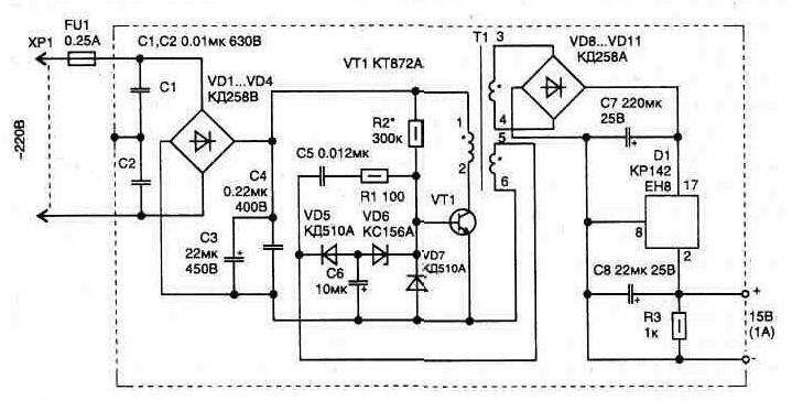
Fig. 5.1. Electric diagram of the switching power supply 15 W
If necessary the secondary winding can be a few (only one shown), and for operation of the oscillator must the polarity of connection of the phase windings 5-6 in accordance with the scheme.
Setting the Converter is to obtain steady excitation oscillator with the input voltage from 187 to 242 V. elements requiring the selection marked with an asterisk "*". The resistor R2 may have a value of 150…300 kω, and the capacitor C5 - 6800…15000 pF. To reduce the size of the inverter in case of smaller withdrawn in secondary circuit power ratings electrolytic filter capacitors (NW, C7 and C8) can be reduced. Their size is related to load capacity ratio:
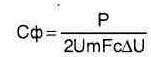
P - power in the load circuit, W;
Um - peak value of the rectified voltage (for acting on the input line voltage 242 In amplitude is 342 In);
Fc - frequency network, to calculate the SOC does it come from 50 Hz;
DU - maximum the magnitude of the ripple of the rectified voltage allowed for the capacitor (taken from the guide: so for C50-29 he is 10…14%, [L], i.e. 34).
The design of the enclosure should provide the installation of the transistor and the stabilizer D1 on radiators, and shielding the entire circuit to reduce radiated noise.
Publication: www.cxem.net