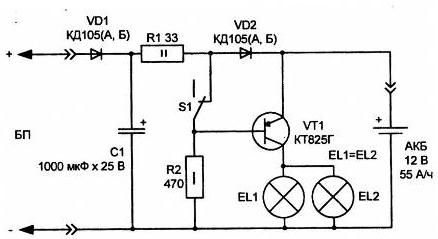
The electrical circuit presented in Fig. 1.3, convenient to use at the cottage and where electricity still comes unstable.

Fig. 1.3. The electrical circuit of the emergency power source
A simple device is assembled on the recommended scheme, will provide automatic back-up light (or other active load capacity of up to 10...12 W) at mains voltage of 220 V.
Transistor VT1 series KT (you can replace specified in the diagram on the transistor CT with alphabetic indices D and E) provides a maximum load of up to 25 watts. It must be installed on the radiator with a cooling area of at least 100 cm2. If you plan less powerful load (up to 5 W), it is possible to apply to the scheme the control transistor type CTL-CTHM.
As a backup power source is used a car battery capacity 55-190 A/h.
As bulbs backup light used automotive lamps the filament.
The principle of operation of the device
The power supply unit (PSU) produces a lower rectified voltage 14 13... V. In the power supply includes a step-down transformer and rectifier bridge.
The ripple of this power supply is smoothed by the electrolytic capacitor large capacity C1.
The voltage from the power supply through the diodes VD1, VD2 and the limiting resistor R1 supplied to the connected battery and charges it weak current. When the value of the charging current 80-110 mA automotive battery can be no harm under the charge for a long time, until about ten days in a row. The voltage drop across the diode VD2 creates a reverse biased to move the base-emitter of the transistor VT1. The transistor is in the closed position and load (EL1, EL2) is de-energized. Switch S1 is used for forced activate the emergency mode. This may be necessary for discharge. Battery or check back lighting (the integrity of lamps).
Establishing
The device in adjustment not needed.
When energy network is disconnected, a stationary power source is de-energized, in the circuit of the base of the transistor VT1 current is supplied through the resistor R2, the transistor is opened and the load is supplied from the battery. Once the flow of energy in the network resumes, transistor VT1 is closed, the load is switched off and the battery charges considered by the scheme.
Details
The resistor R1 brand MLT-2, resistor R2 - type MLT-0,5. The battery and lamp the load is connected to the device insulated stranded network wires with cross section not less than 1 mm and with a minimum length (to reduce losses energy in the wires). The capacitor C1 of the brand C50-24, K50-ZB or other, for a voltage not less than 25 V.
The best option for the step-down transformer mains power supply - universal power transformer CCI 127/220-50-12.
Author: A. P. Kashkarov


