


")

The development of the proposed SMPS was conducted based on the prototype described in the article by E. Haino and E. Moskatova "High-power pulse power supply" in "Radio", 2004, No. 9, pp. 31, 32. Pre-set the objective of increasing the power output three times when maintaining the principle of operation and low cost of the product thanks the use of common components. that is why preference was given to the control of the switching transistors with saturated of the transformer.
The device incorporates resistors in the circuit to positive The OS instead of using a driver chip with numerous components of the "binding". In addition, the base current of the bipolar switch transistors is many times greater than the maximum allowable output current modern driver circuits, such as the IR2110, IR2113 and similar. It requires approval of the chip with the introduction of transistors Modnaya the matching stage and the auxiliary source of power, thus no such advantage of SMPS, as a small number of components. Instead of cheap and common bipolar transistors could be applied powerful MOSFET or IGBT, but then would disappear another advantage is the low cost of the components.
The conversion frequency of the prototype with no load is 9 kHz, so his pulse transformer is heavy and makes whistling sounds. We offer SMPS does not have this disadvantage, because its minimum frequency conversion - 30 kHz.
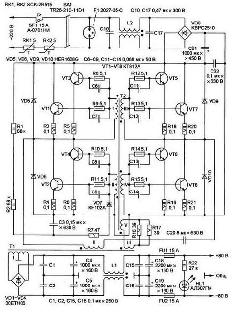
The diagram of the SMPS shown in the figure. The basis SMPS - self bridge voltage Converter with anasasis powerful transformer T1 and saturated low-power transformer T2, the use of such converters is a well known and widespread solution, it used in electronic transformers, ballasts and energy-saving lamps other devices, but these devices are lower power compared to offer.
Main technical characteristics:
- supply voltage, .....176…253;
- nominal output voltage, V.....2x80;
- maximum power load, kW.....1,5;
- the greatest efficiency of the device, %.....94;
- conversion frequency with no load, kHz.....30;
- weight, kg.....4,7.
Due to the fact that USC has its own overcurrent condition, there is no need of this function in SMPS. The conversion frequency is not constant - it is the higher, the more the load capacity. The resistors RK1 and RK2 limit the inrush current charging the oxide of the capacitor C21 for inclusion in the network.
To switch the unit in the event of an accident is the switch machine SF1. Gas spark gap F1 protects your device from over-voltage supply network. On the capacitors. C10, C17 and the two-winding inductor L2 is assembled U-shaped filter prevents high frequency noise from SMPS in network.
Diode bridge VD8 rectifies the alternating voltage, and the capacitor C21 him smoothes, capacitor C22 bypasses the rectifier output at a high frequency.
Resistors R1, R2, R7, the capacitor C3 and the diacs VD7 assembled relaxation a generator that produces pulses that are required to run the generator after power-up and restore conditions for the emergence generation after her breakdown.
Resistors R8-R15 limit the base current of the switching transistors VT1-VT8, capacitors C6-C9, C11-C14 accelerate switch. Diodes VD5, VD6, VD9, VD10 damp the surge transients. Resistors R3 - R6, R18-R21 in the emitter circuits of transistors level of flowing current. Capacitor C20 fixes the magnetization of the magnetic circuit of genesisuses of the transformer T1 constant current.
Through resistors R16, R17 formed a chain of positive feedback from the output of Converter (with the winding III of the transformer T1) to its input (coil V transformer T2). The resistance of these resistors, the number of turns of the windings, the size and magnetic properties of the material of the magnetic saturating transformer T2 depends conversion frequency that can be calculated by the formula:
where F is the frequency, kHz; U is the amplitude voltage pulses on the V winding of transformer T2,; Was - induction of saturation the switching transformer T2, T; q - duty cycle; Sc - area cross-section of the magnetic circuit of the transformer T2, cm2; W is the number of windings V transformer T2; - the fill factor of the magnetic circuit of the transformer T2. for ferrite almost reaching the unit.
Diode bridge VD1-VD4 straightens pulse voltage winding I of the transformer T1. Capacitors C1, C2, C4, C5, C15, C16, C18, C19 and winding the throttle L1 smooths high-frequency and low-frequency output voltage ripple.
Fuses FU1 and FU2 provide protection from the slow increase of the current, loads in excess of the allowable limit. HL1 led - indicator light device, a resistor R22 - current limiting.
The design of the SMPS is arbitrary, the relative positions of the components is not critical, although it is desirable that each of the diodes VD5, VD6, VD9, VD10 was posted perhaps closer to his pair of transistors VT1VT3, VT2VT4, VT5VT7, VT6VT8. source mounted Assembly is assembled.
Switch-automatic AND-NM (SF1) production Sang. Mao Enterprise Co., Ltd., the current opening 15 A and a rated voltage of 250V, can be replaced by A-A, a-H, A-0710W, CBLS2A15, M-W.
Thermistors SCK-2R515 (RK1 and RK2) can be replaced by MS32 5R020, MS32 or 7R015 similar NTC thermistors with a maximum current of at least 15 A and the nominal resistance of 5 to 10 Ohms at 25°C.
Rocker power switch TR26-21C-11D1 (SA1) to replace or SWR74 power switch MK-521A/N. Gas discharger 2027-35-C (F1) replace B88069-X2380-S102, B88069-X370-S102, V-H, FS04X-1JOS or FS04X-1JMG.
Instead AT (VD1 - VD4) suitable diodes 80E8U04, DSEI30-06A, HFA25TB60, Part no rhrg3060. Each diode is mounted on a separate heatsink cooling area the surface 90 cm2.
Diodes HER1608G (VD5, VD6, VD9, VD10) interchangeable on IT, 15ETX06S, HFA25TB60, Part no dsei12-06A, FES16JT, and a diode bridge. SWРС2510 (it is necessary to provide heat sink with a useful area of at least 50 cm2) is any of GBU25M. BR2510, BR2510W, SWРС3510 or MW.
A dinistor VD7 - any of CNA - CNV and NA - NB; the last three it is preferable for the operation of the SMPS at elevated temperature. Also suitable import diacs DB-3 or D8-4 with voltage enable 32 and 40 In accordingly Switching bipolar transistors VT1-VT8 installed on each the heat sink with a cooling surface area of 140 cm2. Instead CTA can use eight of the same type of transistors TA, CTB or CTA.
Capacitors C1-C3, C15, C16, C22 - polyethylene terephthalate MER or MEF (a C20 composed of eight parallel-connected capacitors MER of 1 UF with rated voltage 630 V. the Capacitors C6-C9, C11-C14 - ceramic. CMB-N, K10-17A-Uw50 K10-17B-Uw50. The capacitors. XU and C17 - V-AM calculated for connection to the AC mains. their allowed to replace capacitors 881131-1105-M, W-S-M, W-S. V-S-M or similar. Oxide capacitors C4, C5, C18, C19, C21 - aluminum K50-6 C50-35 or similar.
All fixed resistors used in the power source - nepravosudnye, for example, MLT, ALT, S2-23 C2-33. Resistors R1, R2, and R22 must have nominal power dissipation 2 W. Resistors R3-R6, R18-R21 - import ceramic series CRL, they may be composed of several parallel United resistors to obtain the necessary resistance and power the scattering.
Pulse transformer T1 is made on the magnetic core size of Sh ferrite. MNM-9, corresponding to the technical conditions of AGO.707.140 TU. Also it is permissible to use the ferrite MNM-17. Winding I of the transformer contains 2 sections of 8 turns bundle of four wires stacked together petv-2 0,5. Winding II contains 28 turns of the two wires stacked together petv-2 0,5, and III winding is a single turn of wire sew-2 to 0.5. All windings must reliably to isolate one from the other Teflon, Mylar or leacockanimal tape.
Transformer T2 is wound on a ferrite ring cores size Chsgs from self electronic ballast energy saving lamps.
Each of the windings I-IV contains four spiral wire sew-2 0,25 and winding V - nine turns of wire sew-2 to 0.5.
The inductor L1 is hand made. It is made by the ring-shaped magnetic core, composed of two identical parts size. Khh, from alsever brand. PM-60. The windings I and II are wound in two PEV-2 2 to fill the window. Instead Sew-2 can be applied wire PETV. The inductor L2 - ready B82726-S2163-N30, which, according to the passport, permits the current to the windings 16 And at maximum the tension between them 250 V.
The inductance of each winding is 2.2 μh.
The fuses FU1 and FU2 - NRT-15A N-15A or similar. Led HL1 - any, preferably green glow.
Assembled from undamaged parts SMPS should earn immediately after switching on. If autogenerate is missing, you need to check the phasing of the windings of transformer T2 and maybe swap the connection of his conclusions V winding or windings III the transformer T1. If the conversion frequency without load significantly different from 30 kHz, this indicates unsuitable material or defect the magnetic circuit of the transformer T2, such as a hidden crack. In this case, the magnetic circuit must be replaced.
Author: D. booth, S. CORBA Yaroslavl region