


")

Modern portable and pocket radios, especially imported as a rule, are powered by two batteries or batteries and stationary conditions be powered from any source with stabilized voltage of 3 V and the allowable current of 0.2 A. the same voltage you need to power and electronic games like "WELL, WAIT a minute" and many other devices. Use the power supply if you try, you can find in a commercial stores, but imported and unreasonably high price, and domestic industry these power sources produces little. In addition, they, as the stabilization of the output voltage, which leads to listening network background.
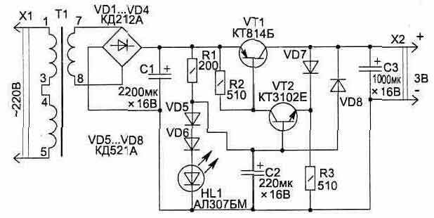
Fig. 5.1
To collect the necessary source anyone who knows how to use a soldering iron, and it does not require much time and high costs.
Here are two ways of constructing such a scheme, collected on different elements, and specific you can choose for yourself, having and based on their capabilities.
In Fig. 5.1 shows a simple diagram of the power supply 3 In (load current 200 mA) with automatic electronic overload protection (With = 250 mA). Level output voltage ripple is less than 8 mV.
For normal operation of the voltage stabilizer after rectifier (diodes VD1…VD4) can be from 4.5 to 10 V, but it's better if it will be 5…6 V, - less power is lost in heat dissipation by the transistor VT1 when the stabilizer.
In the scheme as a source of reference voltage used HL1 led and diodes VD5, VD6. The led is at the same time and the operation of the power supply.
Transistor VT1 is mounted on a heat dissipating plate. The transformer T1 can be purchased from unified series TN favourite, but better use the most compact TI-127/220-50 or T-127/220-50. Suitable also many other types of transformers with a secondary winding 5…6 V. Capacitors C1…NW type K50-35.
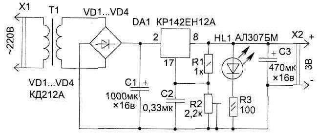
Fig. 5.2
The second scheme (Fig. 5.2) uses the integral stabilizer DA1, but unlike transistor of the stabilizer shown in Fig. 5.1, for normal operation of the chip is necessary that the input voltage exceeded the output of not less than 3.5 V. This reduces the efficiency of the stabilizer at the expense of heat dissipation on the chip - low output voltage of the power lose the power supply will exceed output to the load.
The required output voltage is set a trimming resistor R2. The chip is mounted on the radiator.
Integrated stabilizer provides lower level output ripple voltage (1 mV), and also allows the use of capacity smaller denominations.
Publication: www.cxem.net