In his designs hams are very often used transformerless low-power sources. Usually, they represent a kind symbiosis parametric regulator and rectifier. Mains voltage in such circuits are used fully (full amplitude), and the excess voltage is extinguished constant resistor that produces power or reactance of the high-voltage capacitor. Both scheme it is difficult to name the best solution, except that with regard to limit of simplicity.
But there is a key diagram of a transformerless source, in which used not the whole amplitude of the mains voltage, but only a small parcel of land - from zero to a certain value. This stabilizer works something like this, with the passage of the sine wave AC output outlet through zero key turns on and remains on until until the wave of the mains voltage reaches a certain value. Then the key is closed.
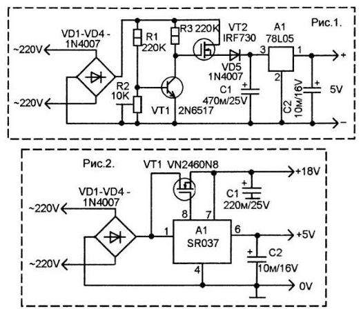
Thus, it cuts off half-line voltage at some level. Then this pulsating voltage is smoothed and stabilized capacitor the stabilizer. In this source there is no damping resistors or capacitors. He just uses only small pieces of half wavelengths. Schematic diagram of the source operating on this principle is shown in figure 1.
Mains voltage is rectified by a diode bridge VD1-VD4.
The output of this bridge there is no capacitor, so there will be pulsating voltage changes from zero to 300 V. the Transistor VT1 comparator, and the transistor VT2 is the key. Resistors R1 and R2 form a voltage divider on the base VT1. The adjustment of the resistor R2, you can set the threshold of opening VT1, for example, equal to 18 V.
While the output voltage of the bridge VD1-VD4 reaches this value, the transistor VT1 is closed. At the gate of the transistor VT2 is supplied gate trigger voltage and it open. The voltage across it and the diode VD5 is held on capacitor C1 and charges it. Then, as soon as the voltage at the rectifier output exceeds the threshold, the transistor VT1 will open and will shunt the gate VT2.
The key VT2 is closed. And appears only on the decline of a pulsating voltage when its value is below the threshold of opening VT1. Thus, C1 accumulates a voltage of about 15...18 V, which comes integrated stabilizer. A1 and the output of the source.
The source according to the diagram in figure 1 provides a stable 5 V at currents up to 100 mA.
Figure 2 provides a diagram of key source for specialized chip SR037. The scheme provides two voltage 18 V and 5 V, both with a maximum current of 30 mA.

Working with data sources should not forget that their secondary circuits have a galvanic connection to the grid, and to take all appropriate measures electrical safety.
Author: Karnaukhov V. T.


