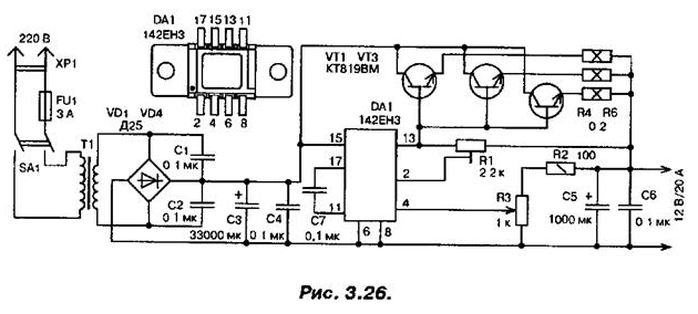
In Fig. 3.26 shows a diagram of a stabilized power supply 12 To 20 A. Mains transformer T1 is designed for a capacity of 450 watts and has a secondary winding 15 V. Primary stabilizer is IC DA1 CES. Resistor R1 set the current limit. Resistors R4....R6 are leveling and made of wire resistors. Transistors VT1 VT3...posted on the heat sink capable of dissipating 100 watts, DA1 chip is also installed on a small heatsink. In case you are not able to install sufficient area of the heat sink for better cooling, you need to install a small additional fan.

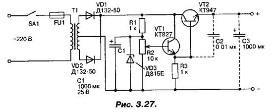
Another simple but powerful power supply, made a powerful compound the transistors (Fig. 3.27), it is suitable not only for charging automotive batteries, but also for powering the various electronic circuits. The output voltage the device is adjustable from 0 to 15 V.

The current depends on the degree of discharge of the rechargeable batteries and can reach up to 20 A. Since the cathodes of the diodes and the transistor collectors are connected together, all these details are placed on one large radiator without insulating strips. Unless there are special requirements for the stability of the voltage, the resistor R1 and Zener diode VD3 from the scheme can be eliminated. Adding capacitance, shown in the diagram by the dotted line, you can use the device as a power supply.
Author: A. P. Seman


