


")

Automotive transceivers when transferring consume significant current up to 20 A. Networking power source for such devices is a serious the problem. In Fig. 3.32 shows the schematic diagram of the power supply.
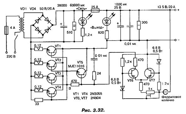
The secondary of the transformer must be rated for a current of 20 A and a voltage of 20 V. the Diodes of the bridge are mounted on the heat sinks, it is better to use power diodes with Schottky barrier.
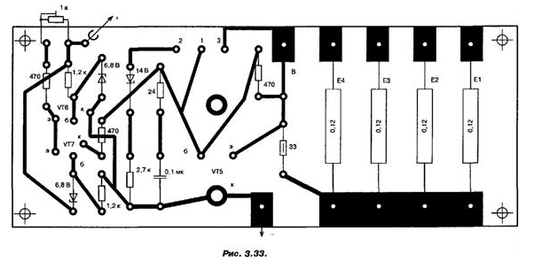
Stabilizer with fault protection transistors VT1…VT7. Output the voltage shall be adjusted by the resistor. The error signal amplifier performed on the differential cascade VT6, VT7. A repeater on composite the transistor VT5 regulates the control transistors VT1…VT4, emitter the circuit which included leveling resistors 0,12 Ω with uniform current distribution across all four transistors (5 each). The network rectifier, filter capacitors, transistors VT1 and VT4… set outside of the Board. Collectors VT1…VT4 galvanically connected to the housing, that allows you to use the chassis as a heatsink without insulating strips. As VT1…VT4 you can use CT, VT5 - CT, VT6 and VT7 - CT with any letter index. The printed circuit Board shown in Fig. 3.33.
Author: A. P. Seman