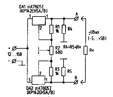
To configure electronic equipment, power reversible electric motors, electromagnets necessary power sources with inversion voltage. The figure shows a diagram of a simple power supply that allows you to smoothly change the voltage at the load from +Uвых to-Uвых.
The power source is made on the basis of two controlled voltage stabilizers DA1, DA2 type mA7805 (LM7805) or their equivalent - CREA(IN). Adjusting the output voltage stabilizers interdependent and implemented by potentiometer R2. So, when we change the value of R2, the voltage across the resistor R4 varies from 5 to 10 In; at the same time the voltage across the resistor R5 is changed from 10 to 5 V. Thus, the output voltage at the terminals AB is continuously adjustable from +5 to -5 V.

Adjustment of the device lies in the selection of resistors R1 (P3)to obtain resistors R4 and R5 when adjusting R2 (when disabled on the required limits of change of voltage on a common bus - 5...10 V and 10...5 V, respectively.
The minimum value of the load resistance is determined by the ratio R load<R4=R5 and can be up to 10 Ohms. The current findings 1 chip installed on the radiators can reach 1.5 a, And the resistors R4, R5 must have a power dissipation of at least 10 watts. Since the efficiency of the power source is low (11...14%), and also for reasons of reducing the power dissipated in the resistors R4, R5, it is desirable to use a higher resistance load. Thus, when R load>100 Ω (R4=R5=100 Ω), the power dissipation of the resistor is 1 W, and the maximum load current is 50 mA (R load>10 Ohm limit load current limit is set to 500 mA).
When R load reduction below minimum (up to a short circuit) Uвых reduced. Damage to integrated circuits during this procedure.
The circuit can be easily altered to a higher output voltage when using integrated circuits series mA7806, mA7809, etc., or their analogs series KREN, 8, 9. When you run the potentiometer R2 on a closed annular core with diametrically summed up contacts and connected to the axis of the potentiometer via a gear motor, the output device, you can obtain a slowly varying sinusoidal voltage or other form.
Author: M. Shustov, Tomsk; Publication: N. Bolshakov, rf.atnn.ru


