The majority of children's electric toy works from galvanic cells and batteries. So often there comes a time when the energy source supply runs low, and no new. The toy ceases to act at all, and children start on your nerves with requests to buy batteries. Such is not happens if you make the suggested power source and connect it to the or another toy. It is particularly suitable for moving toys, for example, the railway. Then the speed and direction of movement of the locomotive with carriages it is possible to smoothly change the control handle of the source.
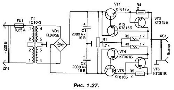
Source (Fig. 1.27) consists of a rectifier and two identical electronic voltage regulator with protection against overload and short circuit in the load. The rectifier diode is assembled on the bridge VD1 by full-wave scheme with an average point. The diode unit is connected to the secondary winding of power transformer T1. consisting of two series-connected identical windings forming a common winding with an average output - this is the mid-point of the rectifier. Rectified voltage is filtered by capacitors C1, C2, United in series and connected to the midpoint. In the end, the output of the rectifier turns out bipolar DC voltage of 12 In a relatively mid-point.

On the output capacitor C2 minus 12 V. these sources connected electronic regulators, voltage-controlled, remove from engine AC resistor R1. Each controller is composed of two transistors (VT1, VT2 and VT4, VT5), forming a compound emitter follower. In the middle position of the engine resistor voltage across it will be close to zero with respect to a common wire. Therefore, the transistors regulators closed, the voltage at the sockets of the connector XS1 no.
When the slider of the variable resistor moves down the diagram, transistors VT1, VT2 remain closed, and VT4, VT5 open. At the output of the power source (connector XS1) appears negative voltage (on the upper circuit on the conductor connector towards bottom). Moreover, the closer to the lower output AC resistor is the engine, the greater the output voltage.
If you start to move the slider of the variable resistor from the middle position to upper circuit on the output, the opposite will happen, will be opened transistors VT1, VT2, and the output of the source appears positive voltage.
The nodes of the protection against overload or short-circuit transistors VT3 and VT6. While flowing, for example, through resistor R4, the current is certain limits (in our case up to 350 mA, the transistor VT3 is closed. As only the load current exceeds a preset value, the voltage drop across the resistor R4 will increase and the transistor VT3 will open. The emitter junction of a compound transistor (the area between the base of transistor VT2 and the emitter of the transistor VT1) will be shunted, and the transistor is almost closed. Output current source sharply limited. As soon as the overload or short circuit disappears, normal operation of the device will be restored.
Instead of transistors CT, CT fit, accordingly, CT, KT815. Diode block CCE can be replaced by CCE or four series diodes CD, CD.

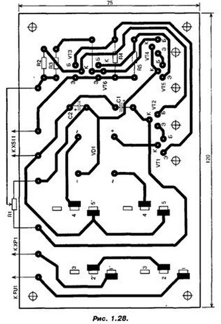
The power transformer may be, except as provided in the scheme, TP20-14 or any other, of a power less than 10 watts and the voltage on the secondary windings 8...12 V at load current to 0.7 A. the Transistors mounted on the heat sinks with a total surface area of about 35 cm2, which is attached by screws to the Board. Current protection depends on the resistances of the resistors R4, R5. It can to increase from 350 to 500...600 mA, reducing the resistance of these resistors to 1,2...1 Ohm, as well as increasing the area of heat sinks transistors VT1, VT5 to 50...60 cm2. The printed circuit Board of this device is shown in Fig. 1.28.
Author: V. Andrushkevich


