Now many use the pocket MP3 players and other miniature electronics powered by one "AA" or "disk" battery (1.5 V). Despite the economy, one element power MP3 player rarely lasts for days. Need to buy a new one, or to use the batteries to charge.
If you spend most of the time use the MP3 player at home, during work or studies, that is, in the place where there is a mains ripple. As a result, the output of the adapter is obtained unregulated voltage 9 V (actually from 7.5 to 10 In). Here and eats them video-game consoles. To this unstable voltage to get stable 1.6 In we will need to make a stabilizer, which will lower the voltage to 1.5 V and it will be to maintain stable.
In Fig. 2 shows the schematic is converted network adapter, you can organize meals MP3 player from the wall outlet. But for this requires special AC adapter (adapter). On sale now often just found a 9 volt adapters to power the 8-bit Telegraph consoles like "Dandy" or "Kanga". These boxes are not very reliable and fail most often because of the broken connector in which is inserted the cartridges with games, or due to breakage or fracture of the printed tracks coming from the chip connected to this connector. Typically, these consoles poorly repaired and, since the cost is relatively low, the return is broken buy a new one, and the power supply (AC adaptor) remains. That's because such a network adapter and 9 volt you can make a stable source to power the MP3 player from the mains.

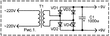
A schematic diagram of a network adapter "Dandy" usually looks like this. as shown in Fig. 1.

T1 is a low-power transformer. On its high-voltage winding (many turns of thin wire) receives voltage from the power supply, and reduced voltage with a low-voltage winding is fed to a bridge rectifier on the diodes VD1-VD4. Capacitor C1 smoothes which already has a built-in stabilizer. The stabilizer is made on the transistor VT1 scheme parametric stabilizer with the current amplifier. Transistor VT1 works as a cascade - emitter follower. Theoretically, such a cascade voltage on the base is equal to the voltage on the emitter, but on the emitter current is greater than, then there is a higher power. Almost the same voltage the emitter will be slightly lower than at the base. This is due to the fact that the emitter the transistor is a p-n junction, similar to the properties of the diode. Therefore, the emitter drops some voltage (forward voltage at the diode), so that the transistor CT in this scheme on the emitter will be a voltage of about 0.6 V less than at the base.
When doing stabilizers in such schemes, the base is usually served voltage with the Zener diode. Given that the emitter falls 0.6 V, we need Zener 1.5+0,6=2,1 V. Such Zener no. There stabistors, but they very rare on sale, and we need to make the scheme available on the detail. Here, for example, diodes available KD522, they are found in almost all electronics, and on sale very freely. On one diode in direct KD522 the direction of the voltage drops about 0.7 V. If you take three of the diode and to include them in series, you just get 0,7x3=2,1 V.
Circuit of a resistor R1 and three diodes KD522 forms a simple parametric the voltage of 2.1 V. This voltage is supplied to the base of transistor VT1 And in its emitter is obtained by 2.1 by 0.6=1.5 V, that is exactly the right voltage, we need to power the MP3 player.
The capacitor C2 is additionally suppresses ripple, and the resistor R2 is additional load transistor so that when the MP3 player is turned off, the transistor not remained without load, and when you turn off the adapter from the wall socket to quickly C2 discharged through R2.
How to do it practically depends primarily on the design of the network adapter subjected to alteration. If you have a choice it is better to take the adapter size bigger to have enough space to install the schema the stabilizer. If there is only a small adapter, and stabilizer in it did not to cram, it is possible to make the stabilizer in a separate housing, for example in matchbox or tape from the film. Then will go one wire from adapter to the stabilizer, and then another wire from the regulator to the MP3 player. But of course it is better when the whole scheme "in one bottle".
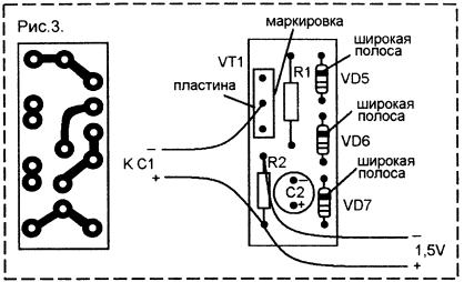
The stabilizer is soldered to a small circuit Board, shown in figure 3. The tracks shown if you look at the cost side of the tracks. and the details - details. Pay attention to the Pinout details. The transistor CT with one hand the housing has a metal radiator plate, and the other coded. On the circuit diagram shows how it should be positioned transistor (solder Vice versa - and the scheme will not work, and the transistor can be spoiled). Diodes KD522 made in striped glass buildings. Broad strip closer to the cathode output (on the wiring harness on it instructed). Capacitor C2 should also solder the correct orientation. If it's domestic condenser type K50-35, then his body near a positive output will be "+". and here at import capacitors wide strip marked with a minus.

In the transistor CT there's a hole under the screw. This hole Board and is mounted in the housing network adapter - drill in the body of the adapter hole and screw with a suitable nut screw back transistor, and the fee is already on it will stay. If you did not have a suitable screw - better to look for, as drill out a hole in the transistor cannot. Connecting the circuit to the rectifier the network adapter is necessary to observe the polarity so as not to confuse plus-minus. The same applies to the connection to the MP3 player.
The MP3 player is powered by one "finger" of the item does not have a connector to connect an external source power. Therefore, you will need to make a dummy battery. You can take thick pencil suitable thickness and cut from it a piece of a bit in length shorter battery life. Then squeeze out the stylus, clean the hole where he was the stylus. Then both ends screw short screw or self-tapping screws - they will instead of contacts. These screws to bring the wires from the power source. It does not reverse the polarity of the connection, and sign on the piece of wood where plus, where's the negative, not to confuse when installed in the battery compartment MP3 of the player. Now to fuel MP3 player from the mains must be removed from it galvanic element and put this dummy with the correct polarity. Then connect the adapter plug into the socket. May still be required in the lid of the battery cover up your MP3 player to saw through the groove in order through which it was possible to deduce the wire, but you can just close the lid.
Author: S. Andreev


