


")

The proposed power supply is built on the basis of chip LM2575T-Adj firm Motorola. This chip is a switching voltage regulator DC regulated output voltage. Conversion frequency (52 kHz) is determined by the embedded generator.
The chip is operable when the input voltages up to 40 V. the adjustable range of output voltage is 1.2…35 V At load current up to 1 A. the Minimum difference between input and output voltage about 2 In, includes built-in protection against over temperature, short circuit in the load circuit and overcurrent.
The diagram of the power supply shown in Fig. 1.
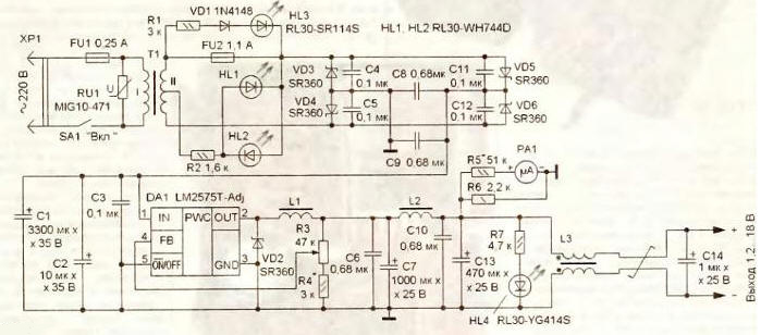
Fig. 1
The power supply provides current up to 1 A at an output voltage 1,2…15 V. When a voltage of 15....18 In the maximum current is reduced to 0.5 And, due to the type applied step-down transformer. If you want output current reached 1 in the entire interval of the output voltage should be applied step-down transformer with a secondary winding voltage of 22 V At the output a voltage of 5 V and a load current of 1 A stabilizer consumes from the rectifier current of 0.23 and its efficiency is about 90 %.
The voltage is 220 through FU1 fuse-link and the closed contacts of the switch SA1 is supplied to the primary winding of the step-down transformer T1. Voltage the secondary winding via resettable fuse FU2 arrives on the pavement a rectifier diode Schottky VD3-VD6. The use of such diodes reduces loss of power to a bridge rectifier in comparison with conventional diodes, decreases thereby heating elements, which is important for the power supply in compact case. Led HL3 red glow indicates triggering a self-restoring fuse FU2, which is required for protect the transformer against overload fault rectifier or chip stabilizer. Varistor RU1 together with fusible link protects FU1 transformer, diode rectifier and stabilizer from pulse and short-term overvoltage.
The ripple of the rectified voltage oxide capacitor smooths large the capacitance C1. Ceramic capacitors C3, C8 C9, and tantalum C2 reduce the level high-frequency fluctuations. This reduces interference coming into the network from pulse the stabilizer. Output voltage adjust variable resistor R3 moving his engine down (the scheme) leads to an increase in output voltage. The inductor L1 is cumulative. C6C7L2C10C13 - a low pass filter, which reduces the pulsation of the output stabilized voltage. Resistor R6 performs a function of load, if the output of the supply of the load is not connected. Glow led HL4 indicates the presence of output voltage more than 2 V. On the microammeter PA1 and the resistor R5 is assembled voltmeter, which measures the output voltage. The inductor L3 reduces the level of high-frequency common-mode the interference. LEDs HL1, HL2 bright white glow illuminated the scale of the voltmeter and simultaneously serve as indicators for inclusion.
Applied fixed resistors for surface mounting, for example, P1-12, RN1-12. Variable resistor - SDR-4 or similar compact linear characteristic, its metal housing must be connected to the common wire, and on the axle to put on the handle of insulating material - chip regulator sensitive to surges on the FB input. Varistor MIG10-471 can be replaced by varistors FNR-14K431, FNR-10K471, FNR-14K471 and similar to the voltage of 430 or 470 V.
Oxide capacitors (except C2 and C14) - import, domestic capacitors C50-35 is not recommended. Capacitors C2, C14 - for tantalum surface mounting. The capacitor C14 is mounted on the output end of the connecting cable for connection to the load. In the absence of capacitor at a working voltage of 25 V it can be made up of two series-connected voltage of 20 V. All other capacitors - ceramic surface mount sizes 0805, 1206. Capacitor C3 soldered directly to the terminals 1 and 3 of the stabilizer DA1. When applying of fixed resistors MLT, S2-23 and ceramic capacitors with wire conclusions overall dimensions of the power unit will increase.
Schottky diodes SR360 can be replaced by diodes MBRD350, SK35. MBRS360T3, MBR350, MBR360. CDB. In the absence of such diodes can be applied to the diodes of the series KD. but the efficiency of the power supply will decrease, and the temperature inside the enclosure will increase. Instead diode 1N4148 you can install any diode from the KD521, KD522 LEDs HL3 and HL4 - any of a series CIPD, CIPD, L-934. LEDs RL30-WH744D (white glow) can be replaced by 504UWC.
Microammeter RA1 - M68501. M4761 or equivalent level indicator the recording-playback domestic tape recorder. Power switch - keyboards IRS-101-1 A3 or IRS101-12C with neon indicator light, but can apply any compact switch is designed for switching voltage 220 V AC. Connecting the power cable to connect load - wire, length 1 m with a cross section of each wire of 0.75 mm2.
Step-down transformer used ready from the electrophone "Icarus". Instead you can apply any similar with overall power 15…25 W, for example, unified TP-8. Homemade transformer can wind on a W-shaped magni-toprovide with the size of the Central core of 6.25 cm2. The primary winding has 1800 turns of wire sew with a diameter of 2 0 of 2 mm, secondary - 155 turns of the same wire diameter of 0.68 mm In the absence of withdrawal from the middle of the secondary winding of the resistor R2 is connected to the bottom under the scheme the conclusion the secondary winding. The resistance and wattage of the resistor R2 you must increase twice.
The inductor L1 is wound on three magnetic cores glued together Kh-6 ferrite N. It contains 12…15 turns of homemade Litz wire consisting of 20 segments the PEV-2 with a diameter of 0.18 mm. Segments are stacked together and recoil with manual winding machine, hand drills, electric screwdrivers or electric drill, running at low speed. The use of Litz wire reduces the power loss in the inductor L1 and facilitates its winding For producing chokes L2 and L3 applied magnetic CHH.5 ferrite NN, the inductor L2 contains 16 turns of wire sew-2 0.68, L3 - 2 turns of the output two-wire cable. Before winding all chokes you need a file to grind off the edges of the yoke and then wrap them with a layer varnished fabrics.
All the elements of the device is placed in a makeshift plastic housing with dimensions 85x56x106 mm, glued boxes for 35 mm film slides (Fig. 2).
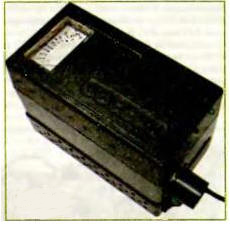
Fig. 2
The placement of the elements in the body is very dense (Fig. 3), because half of the volume is a step-down transformer and a microammeter.
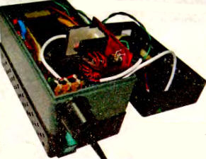
Fig. 3.
In the lower part of the walls of the housing are drilled about one hundred vents with a diameter of 2.5 mm. Most of the components placed on the circuit Board dimensions 46x72 mm Mounting elements is carried out in hinged manner. Lead elements placed on one side of the Board (Fig. 4), and the elements for surface mounting - on the second.
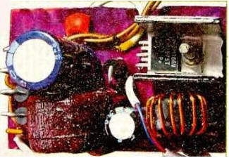
Fig. 4
Varistor RU1 soldered to the terminals of the transformer. On the upper part of the body installed microammeter, for him to make a rectangular box of the relevant size. LEDs HL1, HL2 glued to the microammeter with two sides so that they highlighted the scale of it. Integral regulator LM2575T-Adj preferably be installed on a heat sink with a total area of 4…8 cm2, made of alloy aluminum or copper.
The assembled configuration of the power supply unit consists of setting the upper bound output voltage selection resistor R4, and a selection of resistor R5 set the maximum value of the measured voltage. Then use exemplary voltmeter spend the graduations of the scale of the built-in voltmeter. If it is necessary that the power supply had protection from overcurrent in various his values, which is important primarily for laboratory use, in series with the inductor L2 is necessary to install multiple switchable resettable fuses.
Author: A. Butov