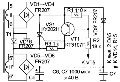
In "Radio" № 6, 2000, an article was published by A. Shitov "Laboratory power source". In this device, I changed the switching node of the secondary the windings of the transformer. His scheme is shown. When turned off SCR VS1 rectifiers VD1-VD4 and VD5-VD8 are connected in parallel, and when on consistently.

This allows you to more evenly distribute the load on the winding of the transformer. Compared with baseline, the node is added only one diode VD16, changed the connection of a diode VD9 (in the diagram it is marked VD9') and reduced the resistance of the resistor R2 to 18 ohms.
Stabilizer DA4 is fed from a separate winding of the transformer, designed for the load current less than 100 mA.
Author: R. Baigabulov, Kuvandyk Orenburg region


