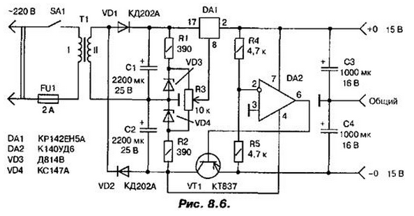
The proposed scheme contains a small number of parts, but despite this, provides a fairly high performance. A simple and uncritical to used to detail makes available its recurrence even for inexperienced ham radio.
Schematic diagram of the power supply unit shown in Fig. 8.6. It is based on integrated stabilizer CREA, which allowed to achieve high parameters the entire device.

The operational amplifier compares the voltage on the shoulders absolute value (the comparison voltage in the connection point of the resistors R4 and R5 with the voltage on the common wire, i.e. with a zero) and, acting as a comparator, amplifies the error signal (the difference between the voltage at the point of junction of R4 and R5 and common wire) and delivers it to the base of transistor VT1. Thus, symmetry shoulder stabilizer is maintained with great accuracy.
The rectifier is formed on the diodes VD1 and VD2 in the circuit with a voltage doubler, which gives the opportunity use a transformer with a secondary winding. The device can use a transformer with a secondary winding for voltage 13...15 VDC At load current up to 3 A. the Diodes VD1 and VD2 - any rectifier, designed for current is not less than 2.5 A. the Transistor VT1, except as provided in the scheme, may be of the type CT, KT, it needs a heat sink surface area of at least 100 cm2. Instead of the operational amplifier COD you can apply CUD, K544UD1. Integrated stabilizer DA1 need to be installed on the same heatsink as the transistor VT1.
Author: A. P. Seman


