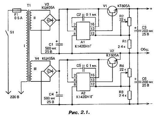
The circuit of the power source shown in Fig. 2.1. It consists of two stable rectifiers operated from a single power transformer T1.

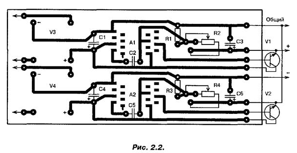
In figure 2.2 shows the printed circuit Board.

The output voltage of the source may vary ±3 V to ±20 V at a current load of 0.5 A. the Coefficient instability voltage of not less than 0.5%/V. Both shoulder of the source is identical and independent. Rectifiers are collected for full-wave bridge circuit using diode assemblies CCA.
Actually stabilizer made on chips KEG and transistors V1 in one shoulder and V2 - arm of the scheme. Adjustable output voltage is variable resistors R2 and R4.
To reduce the ripple of the rectified voltage at the input of each stabilizer included the big capacitors. The transistors V1 and V2 installed on blackened aluminum finned heat sinks. The area of each radiator 400 cm2. The variable resistors R2 and R4 type SPO-0,5.
Electrolytic capacitors - C50-6. The transformer T1 is wound on the yoke Sh. Winding I contains 1210 turns of PEV-1 is 0.3, winding II and III - 90 turns of PEV-1-0,67.
Author: A. P. Seman


