


")

Based on the network adapter from unnecessary outdated phone with the function automatic determination of the number of the caller is collected the Z80A microprocessor, to make a simple power supply with linear regulators that provide the output of the two stable voltage of +5 V and +8 V when the total current loads up to 500 mA. It can be used to power the digital and analog devices, to recharge the batteries of mobile devices for feeding baby toys.
Schematic diagram this BP is shown in Fig. 1.
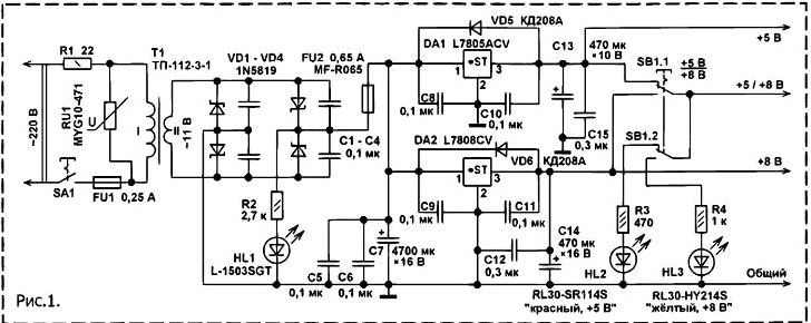
Voltage AC 220 through the closed contacts of switch SA1 and the protective resistor R1 and the fuse is supplied to the primary winding of the mains transformer T1.
Since the secondary winding this transformer is removed reduced to 11 In the AC voltage, which is rectified by the bridge rectifier collected at the Schottky diodes VD1 - VD4. Use such diodes reduces the power loss in the diode rectifier and about 1 In increases the voltage on the filter capacitor C7. Resetable fuse FU2 protects step-down transformer from overload.
Since the power supply was mounted in a compact housing, the maximum load current for a given the transformer for the purpose of improving the reliability reduced from 0.8 to 0.5 And A. Diodes VD5, VD6 protect chips from damaging reverse voltage that may be on the outs chip, if the voltage on the plates of the capacitor C7 will be lowered faster than the output voltage of the stabilizer, for example, because of the short circuit rectifier or loss the capacitance of the capacitor C7. A varistor protects RU1 transformer and Schottky diodes from the surge voltage.
The power supply scheme Fig. 1 comprises two linear regulator, assembled in an integral the circuits DA1 and DA2. First provides a stable output voltage +5 V, the second the stabilized voltage +8 V. the Total current of the connected loads can to reach 0.5 A.
At higher current polymer resettable fuse FU1 is heated and enters the high impedance state. Switch SB1 can to select the voltage supplied to the load: +5 V or + 8 V. In this case, if SB1 is in the "+5 V", lit led HL2, if in position "+8", HL3 will Shine. Also, in addition to the maximum permissible total current of the connected loads no restrictions on the simultaneous use of two stabilizers.
For example, the output channel "+5 V" can to install the USB socket and charge pocket Flash player, battery of a mobile phone, a camera, and the channel "+8" to the time used to power the radio. This PSU installed resetable fuse nominal operating current a little more than the declared maximum of 0.5 A.
The fact that in compact case with the high current step-down transformer noticeably is heated, the temperature in a compact body increases, which causes what resetable fuse is triggered at a lower current.
When triggered the fuse remains steady light HL1, which indicates the presence of mains voltage supply.
Power supply regulated output DC voltage from 1 to 9 In, assembled on the Fig. 2, allows you to connect the load, consuming up to 1.6 A.
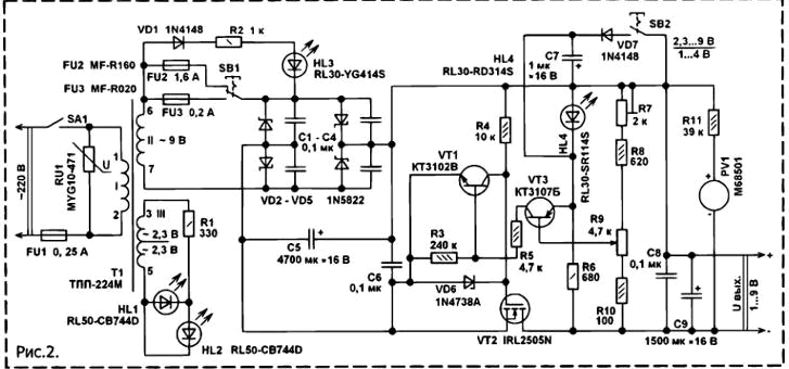
The unit is protected against overload and short circuit in the load circuit, and protection from high voltage AC power. Runs this block power as follows. The voltage of the alternating current through the fuse FU1 comes to the primary winding of the step-down transformer T1. Reduced to 9 In the voltage AC is removed from one of the secondary windings of the transformer and through one of polymer resettable fuses or FU2 FU3 comes on the pavement a rectifier diode Schottky VD2 - VD5. Ripple the rectified voltage is smoothed oxide high-value capacitor C5, after which the voltage is supplied to the compensation voltage stabilizer, implemented entirely on discrete components.
Adjustable compensating stabilizer implemented on hybrid technology - field and bipolar transistors [1]. It is characterized by a very small saturation voltage (minimum voltage between input and output), which when testing this stabilizer load current 2 A, does not exceed 60 mV. It ten times less than the compensation stabilizers traditional type, for example, popular series Kreh, **HH and considerably less (10…30 times) than that of the chip linear voltage regulators with low minimum voltage between input and output.
The rectified voltage is supplied to the source of the powerful field of mos transistor VT2. Because to acquire the n-channel a powerful field-effect transistor with a low threshold voltage of opening the gate-source much easier than the R-channel, the transistor had to install in the negative power supply circuit.
Opening voltage is supplied to the gate of this VT2 through R4 are connected to the General advantage of the food chain. Such a method of controlling the field-effect transistor in back-to-back stabilizer does not require the adoption of special measures to start, which greatly simplifies the design.
Works compensating stabilizer as follows. An increase in the input voltage or decrease of the load current, the output voltage also seek to widen. This leads to the fact that VT3 opens strongly, hence, stronger will open and VT1, which, continue chain gate-source VT2, opening lowers the voltage VT2, the channel resistance the source-drain VT2 increases, the output voltage decreases. Adjustment of the output voltage perform a variable resistor R. 9.
The Zener diode VD6 with voltage stabilization about 8.2 To protect the field effect transistor from damage. Switch SB2можно to select the output voltage range 1…4...9 2.3 V. When open contacts in SB2 as a source of reference voltage the led works HL4 red the color of the glow, the output voltage can be set in the range of 2.3-9 V. When the closure of the contacts SB2 source the reference voltage will be a silicon diode VD7, and the output voltage can be set from 1 to 4 V.
It should be noted that structures laboratory power supply units with a minimum output voltage 1 In relatively few. On the microammeter needle PV1 made voltmeter the output voltage. Switch SB1 can
current tripping. The HL3 led green indicates triggered self-healing fuse. A varistor protects RU1 step-down transformer and diode rectifier surge network.
SuperBright LEDs HL1 and HL2 blue glow indicate that the unit power plugged in, and also highlight the scale of the voltmeter. used in the power supply (Fig. 2) a voltage regulator with a slight modification can be used in blocks power is calculated for a load of 10…15 A.
This requires a parallel C5 two more of the same capacitor, Schottky diodes use the appropriate current, for example, 16 amp MBR1645 mounted on heat sinks. Of course that all high current connections must be made "thick" wires, a step-down transformer must be appropriate dimensional power with high current secondary winding.
The details of the designs. Fixed resistors, you can apply a compact total apply any type, for example, C1-4, MLT, S2-23 appropriate power. Trimmer resistor R7 (Fig. 2) is any compact, preferably closed design. In place of the variable resistor R9 applied trimpot JS4-1 hermetic enclosure. Good stability of the output voltage can be obtained and with other similar resistors, for example, SDR-96, JS4-2M, the CST-1 or smaller wire. PPB-1A, PPB. Varistors MYG10-471 can replace FNR-C, FNR-14K471, FNR-20K431, TNR10G471.
Oxide capacitors - import analogues C50-35, K50-68. The rest of the ceramic on the operating voltage of not lower than 16 In type K10-17, K10-50 or in SMD version for surface mounting. Capacitors C8 - SP (Fig. 1) is mounted directly on the leads of the chips. Instead of diodes with barrier Schottky 1N5819 can to install similar SM5819, MBRS140TR, MBRS140TRPBF, SR360, 1N5822.
Powerful 1N5822 Schottky diodes (Fig. 2) can be replaced trehearne SB360, MBRS360T3, MBRD350, MBR340 and other similar. Mentioned types of Schottky diodes made in different buildings. Diodes KDE you can replace any of the series CD, CD, CD, PART NO 1N4001 - 1N4007. Diodes 1N4148 can replace 1N914, or 1SS176S any of a series KD, KD521, KD522 Instead of the Zener diode 1N4738A suitable BZV55C-8V2, TZMC-8V2, SC, SH, SC. The LEDs can be applied to any types of General application for example, series . CIPD, CIPD, CIPD, L-1503. Instead chip part no l7805acv can set CREN A, b, MS, MS, LM330T-5,0, LM2940T-5.0 TO, and LM9073 other similar [2]. Instead of chips suitable L7808CV integrated stabilizers MS, UVI2940 to 8.0, and similar to the output voltage of +8 V and the load current is less than 0.5 A.
Both devices are mounted on a common heatsink from dural plate 80x50x2 mm Heat sink flanges circuits are isolated from the heat sink mica spacers.
This is done to prevent accidental unwanted short circuits.
In addition, the heat-dissipation, representing the portion of the wall the housing, with the outer side is covered with black insulation varnish.
Before painting the metal plate is treated with emery paper and cleaned with acetone.
As a lacquer you can use black nail Polish or enamel. Instead of the transistor CTV you can install any of the series KT3102, CT, SS9014, WS Instead CTB either will work CT, CT, SS9015, VS. Transistors of different series have the differences in the Pinout.
In place of the transistor VT2 is applied a powerful n-channel field-effect transistor with insulated gate type IRL2505N.Transistor this type is controlled by the voltage logic level, has a resistance the open channel of 0.008 Ohms maximum DC current at 25°C 104 And (to be understood as a constant current for a period of not more than 1 MS), the maximum voltage drain-source 55 in, made In plastic housing. TO-220 this design it is possible to replace, for example, such as IRL3705N, or IRLZ44 to find a suitable table [3]. Field-effect transistor mounted on the heatsink.
When it is mounted it is necessary to take appropriate measures to protect it from breakdown of the insulator shutter static electricity.
The Pinout of the mentioned types of field-effect transistors on a standard gate-drain-source. Microammeter used miniature from the level indicator the record/play old domestic tape recorder. Switches - P2K, latching position, loose groups of contacts are connected in parallel.
Step-down transformer type. TP-3-1 no-load voltage turn on the secondary winding In about 11 can be replaced. TP-2, TP-17. TP-6.
Step-down transformer type. CCI-M - old impulse power supply from the Soviet electronica MC". Transformer has two secondary windings are designed for different current.
Less low-voltage winding to the output circuit voltage of about 5.5 In
used to power led lights. A rectifier connected to the secondary winding with pins 6, 7. With such a transformer, the power supply (Fig. 2) capable of delivering the voltage to 6.5 V at load current of 1.6 A and to 9.10 In with a load current of 0.5 A.
Instead of such a transformer can be applied unified type TPP-6 or TPP-6.
Literature
1. Butov, A. L., a Backup power source for pocket Flash player. - Crystal set kit,
2009, № 10, p. 17 -18.
2. Domestic integrated stabilizers and their foreign counterparts. - Crystal set kit,
2010, vol. 10, No. And No. 12.
3. New N-channel field key
the transistors of the company IRF. - Crystal set kit,
2010, No. 2.
Author: Butov, A. L.