Many instruments and devices made operational amplifiers require the bipolar power supply with relative large potential difference. This imposes significant restrictions on the use of such equipment in the field, or you want to apply other schematics, often to the detriment of quality.
Here's a description of a simple two-pole Converter, which allows from the battery source voltage 6 To obtain a stable bipolar a voltage of +20 V, load current up to 50 mA for each pole efficiency Converter more than 60%.

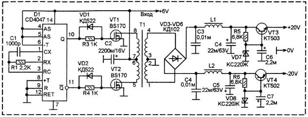
On the chip D1 (CD4047) made by the generator of the symmetric out-of-phase pulses. IC CD4047 is a combination of inverters for build multivibrator and trigger-shaper-of-phase signals the symmetrical shape. As far as I know, the domestic industry counterparts in series CD4047 C or C releases. Although, maybe I'm wrong.
So, D1 generates an anti-phase pulses with a frequency of about 80 kHz, the frequency set chain R1-C1. Anti-phase pulses are removed from the terminals 10 and 11 D1 and enter keys on field key transistors VT1 and VT2 low power (they have a body like KT3102).
In the stock chains VT1 and VT2 included primary winding 5-6 and 7-8 pulse the transformer T1. Connected together by the pin 6 and 7 of these windings connected to a power source. - the positive end of the battery 6 V (battery not shown). With the secondary windings 1-2 and 3-4 is removed AC voltage at the rectifier VD3-VD6. Mid-point of the secondary winding 2-3 are connected to a common drawback.
The circuit can be made in two versions - with a common negative conductor for the primary and secondary circuits (as shown in the diagram) or not galvanically dependent primary and secondary circuits.
In the second case, all circuits common wire to the right of the transformer (the scheme) is not connect the common wire circuits shown in the diagram to the left of T1.
Coils L1 and L2 suppress RF interference. Capacitors C4 and C5 suppress pulsation.
Transistors VT3 and VT4 made simple parametric stabilizers. Output voltage equal to the voltage stabilization VD7 and VD8.
The transformer T1 is wound on a ferrite ring external diameter of 23 mm. First secondary winding is wound 40+40 turns of wire sew 0,43. Then, on its surface is wound the primary winding 6+6 turns sew 0,96. Winding can to perform a winding two wires. Part of the transformer windings connected in series (end winding 1-2 connected with the beginning of the 3-4, the end of 5-6 is connected to the start winding 7-8).
Coils L1 and L2 are wound on a ferrite rings with a diameter of 7 mm. They contain 30 turns of wire sew 0,43.
Author: V. A. Toropov


