This device, which uses a conventional coil starter from the car, generates the voltage from 5000 to 30000 V. The circuit generates a pulsed high voltage at low frequencies and is suitable for observation or photography of the aura of small objects: coins, leaves, insects, and other biological objects, including fingertips.
Many researchers believe that too low frequencies are not suitable for observation of the human aura, and recommend the use of medium or high frequencies in the range of 2000...10000 Hz. Actually at a very low frequency signals can occur short-term discharges that can cause electric shock. If this happens, adjust glass or plastic plate in the electrode on thicker.
If you put your finger on the electrodes, tingling sensations and burning quite normal.
The device is powered by AC power, so you need be careful to avoid electric shock.
For security, you must use an isolation transformer.
Attention! Do not touch the parts of the operating device, if it is connected directly to the AC! Always use an isolation transformer. If you are photographing your fingers or palm of the hand, always wear shoes with rubber soles. If the feet are in contact with the ground, the electric current flows through the body, which can lead to serious the electroshock. Replace the glass thicker, if you feel that you hit current.
The principle of operation
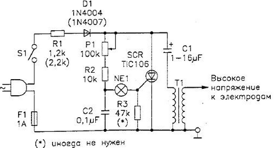
Diagram (Fig. 2.50) consists of a relaxation oscillator using neon a lamp and a silicon thyristor. Capacitors C1 and C2 are charged with the rectified AC line voltage through a resistor R1 and potentiometer P1. As soon as the voltage the capacitor C2 reaches the point of ignition of the neon lamp, is formed impulse current, which is transmitted to the thyristor. The thyristor opens, completing the circuit, formed by the capacitor C1 and the high-voltage winding of the ignition coil. Capacitor C1 discharges through the ignition coil current pulse of great strength. In this case, the secondary winding of the ignition coil is formed impulse a high voltage.

Fig. 2.50 Kirlian Apparatus
After discharge of the capacitors C1 and C2 neon lamp turns off, and with it is locked to the thyristor. Begins a new charge cycle, and describes the process repeats.
Time cycle of charge and discharge can be adjusted by the potentiometer P1. When the values shown in this project, the oscillator operates at frequencies between 100 and 1000 Hz. Reducing the values of capacitors C1 and C2 to 1 µf and 0,047 µf, to increase the frequency, in this case, however, will lower the output power of the circuit.
The high voltage induced in the ignition coil, depends on the voltage, to which charging the capacitor C1. Increasing the voltage on the capacitor can to raise the output voltage from 4,000 to 30,000 and above.
Since the currents in the secondary winding of the ignition coil is very small, which is formed high voltage is not life threatening, although when you touch the coil can severe shock. Note that the device is not isolated from AC. This means that the generator should greater caution. For additional security it is recommended to connect an isolation transformer.
Assembly
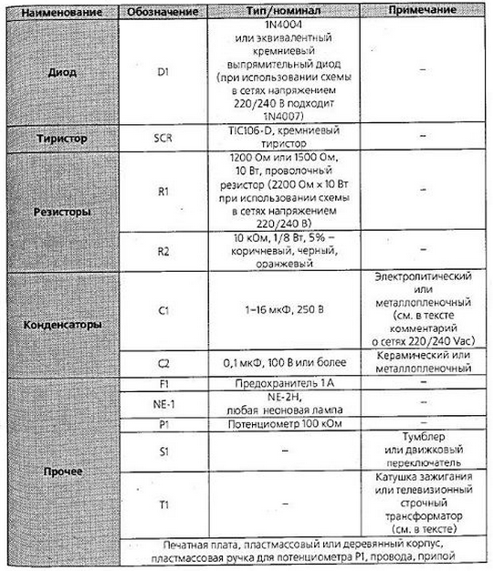
The list of items is presented in table. 2.12.
Table 2.12. The list of elements

The resistor R1 - wire. Its value can be changed depending on the voltage in AC. The values in parentheses are for the mains with voltage 220...240 V Electrolytic capacitor C1 should be a capacity from 2 to 16 UF. It determines the amount of energy transferred to the ignition coil at each impulse, and therefore also determines the power output of the device.
In this project you can use the ignition coil commonly used in car. You can use any type - the only difference between these coils is the value of the output voltage, which can vary over a wide range.
The thyristor must be mounted on a small heatsink, whose role it will play normal metal plate. Type thyristor should be chosen with the expectation that he was able to withstand the amplitude of the mains voltage.
When powered from the mains voltage of 117 In as C1 must be used electrolytic metal film or a capacitor with a rated voltage not below 250 V. If the circuit will be powered from the network 220 or 240 V, the value of working the voltage of the capacitor should be at least 400 V.
The scheme should be placed in a plastic housing, so as to defeat electric current. Metal case cannot be used.
As of the transformer T1 will fit any isolating transformer with the ratio of turns of the windings 1:1, calculated on work from your network. The output of the transformer shall not be less than 20 watts.
Attention! Check the value of the resistance between the windings for the safe operation of the scheme it should be not less than 2 MW. Don't forget about the above warnings to ensure safe the use of the device.
Author: N. With.Braga


