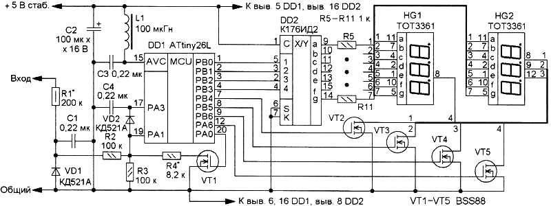
This voltmeter is designed to be embedded in a regulated laboratory power supplies. He carries out the measurement and indication on the four digit led semielemental indicator voltage in the range 0...99.9 V. This interval is divided into two sub-bands: 0...9.99 per and 10.0...99.9 V, and the switching is carried out automatically. The indicator does not use a decimal point, so the separation of the units and tens of volts from tenths to hundredths of a volt is one of the "redeemed" by order of the indicator. Diagram of the device shown in Fig. 1. It is based on a microcontroller DD1, working on the program that you will be able to take the link at the end of the article.

Fig. 1
Measurement of voltage and converting the digital code is embedded in the microcontroller DD1 10-bit ADC. Diode VD1 protects its input voltage from the negative polarity and the diode VD2 limits the voltage across it at 3.1...3.3 V. the Inductor L1 and capacitor together form a NW filter analog supplies microcontroller DD1. Capacitor C1 reduces the noise level at the ADC input, and the capacitor C4 will get RA3 output of the microcontroller, which is present exemplary voltage for the ADC (2,56) set programmatically.
While the input voltage is less 9.99 per the value in the ADC data registers less than the set threshold and the output RA microcontroller low level. Therefore, the transistor VT1 is closed and the resistors R1-R3 form a voltage divider with a ratio of 0.25. In this case, the "glow" of the first and second level indicator HG2, which indicate hundredths and tenths of a volt, respectively. The third category is suppressed, as it is a separation, "lights," as the first digit of the indicator HG1, which is in this case, the third category of indicator voltmeter, it displays the units of volts. If the input voltage reaches the value of 10 V or more, the output RA microcontroller will set the high level, the transistor VT1 will open and parallel to the resistor R3 through a low resistance drain-source on-state of the transistor is connected to the resistor R4, reducing the transmission coefficient of the resistive voltage divider R1-R4 ten times - a 0,025.
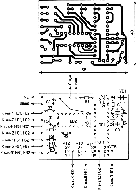
In this case, the "glow" first (tenths of a volt) and third (units of volts) level indicator HG2 (the second is the separation and suppressed), and the first digit (tens of volts) indicator HG1. Most of the parts except the LEDs mounted on the PCB of one-sided foil fiberglass, a drawing of which is shown in Fig. 2.

Fig. 2
The device incorporates oxide capacitors C50-35 or imported, resistors MLT, S2-23 transistors BSS88 interchangeable on BS170P, CPA. You can apply the same four-digit, two-digit or four single-digit led semielemental indicator with common cathode. Choke L1 - DM-0.1 or imported AS, on the Board it is installed between pins 5 and 15 of the microcontroller from the printed conductors. Powering the device from a stabilized voltage source, for example, IC 78L05 regulator connected to the output of the rectifier power supply. But we should remember that the maximum input voltage to the regulator 78L05 is 30 V. the Average current consumed by the device is about 12 mA. The building is reduced to the selection of resistors R1 and R4. First, by feeding a voltage of about 5 V and controlling its exemplary voltmeter, selection of resistor R1 sets the indicator to the desired value. Then increase the input voltage to 15...20 V and a selection of resistor R4 also set the indicator to the desired value.
Program for flash microcontroller
Author: M. Ozolin, Krasnyi Yar, Tomsk region; Publication: www.cxem.net


