This power supply has a fairly wide range and stability the output voltage.
Main technical characteristics:
- Nominal output voltage with a tolerance of ±5 %, .....3; 4; 5; 6; 7,5; 9; 12;
- The maximum load current, And.....0,25;
- The amplitude of the ripple, mV.....10;
- External dimensions, mm.....77x57x50;
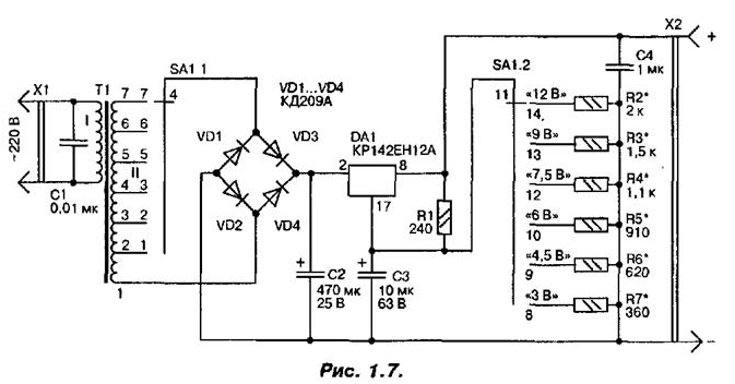
The diagram of the power supply shown in Fig. 1.7. The AC voltage from partitioned winding of the mains transformer T1 through the contacts of switch SA1.1 (depending on the selected limit) is supplied to the diode bridge VD1 VD4... and rectified them. The rectified and smoothed by the capacitor C2, the voltage receives further input 2 circuits DA1, representing the integral stabilizer with adjustable favorable voltage. With its output 8 the stabilized voltage is supplied to the output terminal x2, the Resistors R1-R7 form a voltage divider. Resistors R2...R7 are switched by switch SA1.2 simultaneously with the bends of the winding sections II mains transformer. Capacitor C3 is required to reduce noise and increase the ratio smooth fluctuations.

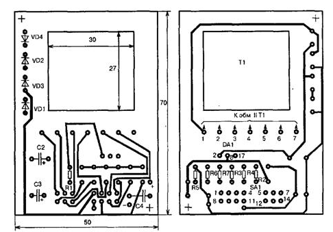
C1 network plays the role of a filter capacitor C4 is the output of the filter block power. Printed circuit Board power supply unit shown in Fig. 1.8. Resistors R2, R7 and... the switch SA1 mounted on the bottom side of the PCB, the other details on the upper. The transformer T1 is mounted on the circuit Board terminals of the windings down and glued to the Board with BF-4. Conclusions the primary winding of the transformer is soldered directly to the pins of the plug (XI). To them and soldered the capacitor C1.

The magnetic circuit of the transformer is assembled from plates Sh. The primary winding (I) the transformer contains 3600 turns of wire sew-2-0,1, and secondary (II) - 368 turns sew-2-0.35 taps on a 166, 200, 234, 268, 302-th turns. All the resistors used in the power supply, - MLT-0,125. The condenser C1 - K73-17 rated voltage 630 V, C2 and C3 oxide C50-35, C4 - km-5. The switch SA1 - slide type PD-41.
Setting it on the Board from the side of the plug eliminates random switching the output voltage when the unit is running with the connected load.
Chip CREA can be replaced by CREB. The heat sink on which she reinforced screw with nut, made of aluminum sheet with a thickness of 2.5 mm.
The establishment of the power supply unit consists of the careful selection of the resistors R2, R7... the divider output voltage. This work is very laborious and, of course, requires special attention and perseverance. The more thoroughly will be picked up each of the resistors of the divider, the more accurate will be the corresponding the output voltage of the power supply.

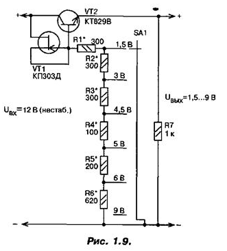
In the absence of the integral stabilizer similar to the power supply unit can assemble according to the diagram shown in Fig. 1.9. Here as a control element applied to the transistor QT, and there is no need to switch winding of the transformer.
Author: Olga Sidorovich


