Now many lovers of high-quality sound reproduction independently make CC amplifiers with very high performance and power output of up to tens of watts. Continuous improvement is subjected to all the links of the amplifying tract, and often assistive devices, switching bodies, indication and p.
The desire to achieve maximum quality indicators UCF increasingly challenging, designers to reconsider its position in relation to power sources. This is understandable - because when a large consumed current of the simplest smoothing filters are no longer able to ensure satisfactory stability of the supply voltage, and this is noticeable affects sound quality. When playing the peaks of the oscillation signal the voltage at the filter output reaches 5 or more, and it makes to provide a supply voltage for the amplifier. But the supply leads to the weighting of the mode of operation of the output transistors of the amplifier and, consequently, to the decrease of its efficiency and reliability.
Therefore, a growing number of hams prefers stable power sources. To the stabilizer is easy to enter the device overload protection that highly desirable, given the cost of high-power transistors and labour the replacement.
What characteristics must have a power source of high-quality the power amp? The most important requirements for power supply UCU, should be considered as providing the required output power for a given the coefficients of stabilization and suppression of ripples, high reliability and the effectiveness of the protection system, the maximum possible simplicity and structure, thermal stability of the protection system and the stabilizer in General.
It is noticed that the stabilizer is designed to work with amplifier power, does not require too much importance to the stabilization factor KST usually leads to considerable complication of the diagram. As shown, high-quality power amplifier works great with stabilizer, having KCT=30. Fluctuations in the supply voltage during the playback signal peaks (when the output power pout=60 W) does not exceed 0.2 and additional distortions, which in these conditions is normal when powered amplifier AF from the unregulated source, did not arise.
Consider issues such as the choice of supply voltage and threshold device protection. Output the voltage u pit (Fig. 1) one arm of the power supply must be equal to:

where Imax is the current value, And when the maximum output voltage swing; IKE us - saturation voltage of the output transistor; RL is the load resistance, Ohm, ROS - resistance feedback resistor in the emitter circuit of the output transistor Ohms.
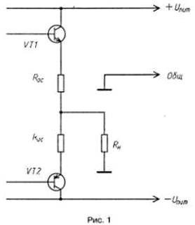
Take RL = 4 Ω, since for this powerful amplifier the most typical case. If specified in inequality substitute numerical values, it is easy to verify that the voltage one arm of the power supply for amplifier 60...80 W is in the range 27...33 V.
Stay on the issue of determining the threshold of the protection system current. Clearly, this threshold should be such that it will distortion at maximum output power. On the other hand, the threshold should not to exceed Imax output the transistors.
As you know, useful the power in the load

where

Based on this the ratio is composed of table values of the threshold However, protection systems current for different values of output power.
Table corresponds to the case where each channel of the amplifier is powered by separate stabilizer (if both of the power amplifier are supplied from a common the source, the threshold needs to be doubled). Roughly we can take However, You = (1,03...1,07)Imax.

On the basis of said and this is confirmed by the practice - it can be concluded that power both power amps from one stable source.
Also important is the question of the choice of type of protection. Protective devices with the stabilization of the current in emergency operation here cannot be used. The fact is that, as a rule, when the circuit of the load circuit through the control transistor stabilizer will flow very high current. If not immediately take steps to limit, possible thermal breakdown of the regulating transistor regulator, and after this is often and output transistors of the power amplifier.
Security device with the closing of the regulating transistor to have a relatively low, but quite fast enough. There are two varieties of such devices - latch and with a "trigger effect". The first automatically return the stabilizer to the operating mode after the cause of the overload. Second leave closed regulating transistor regulator, and return it to the stabilization mode after eliminating the fault external impact.
In our view, the device latch undesirable to use to protect the power amplifier. If the overload is cyclical in nature (for example, when the soundtrack is at maximum level), power to the amplifier will be do intermittently because of periodic triggering of the protection system. This will lead to a repetition of the transition process in the amplifier, which can cause its failure.
Preferred devices "trigger effect". They very effective in the process of building, testing and repair of amplifiers when the probability of an accident is quite high.
With all the above reasoning was developed by the stabilizer, which is it is shown in Fig. 2.
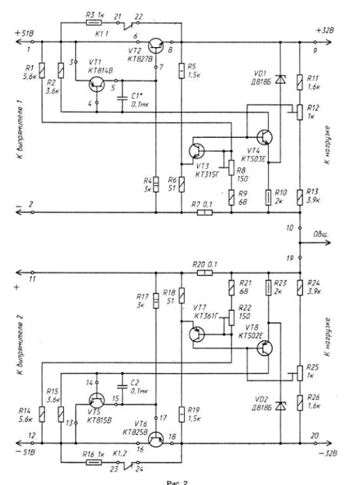
The stabilizer is made by the compensation scheme with the regulatory the element of the composite transistor. Both shoulders of the stabilizer circuit is the same.
Applying to the control element of the Zener diode DB having a negative TKN stabilization, has drastically reduced temperature drift of the output voltage. The use of transistors of different structures in the comparison device (VT4) and regulatory element (VT1) leads, on the one hand, and the need to introduce the circuits of the stabilizer. On the other hand, such a construction gives some advantages. In particular, for actuation of the protection system need only short the switching pulse for reliable closing of the regulating element the stabilizer. This condition is very steadily and there is no need for transistor protection system after VT3 her response was always open.
A chain running is the R3 resistor, shunt the regulating element and the plug contacts K1.1 time relay (Fig. 3). In the initial state (the power supply is de-energized) contact K1.1 and K1.2 relay K1 shorted. After power-up for about 1 starts with the stabilizer. Then the relay is activated, the contacts open and the trigger circuit is disabled.
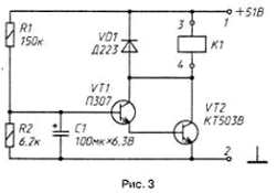
In the event of an overload or circuit load circuit voltage drop at the resistor R7 opens the transistor VT3. This begins to close the transistor VT4 followed by the transistors VT1 and VT2. Reduction the voltage at the emitter of the transistor VT3 leads to further his opening, and avalanche control element is closed (relay K1 remains enabled). After activation of the protection system the output voltage and the current through the load circuit is very small. Even when warmed up to 80°With the body of the transistor VT2 they do not exceed 2 mV and 100 μa.
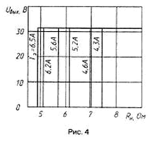
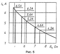
For translation of the stabilizer to the operating mode after the cause of overload need a short time to turn off the power amplifier. In Fig. 4 and 5 show experimentally taken graphical dependence of the output voltage and current the load from the load resistance for different values of the threshold protection systems.
To fully power supply decoupling for each channel of the amplifier is provided a separate stabilizer. Rectifiers are made by depolymerizes bridge circuit with a smoothing capacitive filters.
Total current transfer ratio composite transistor VT1 and VT2 should not be less than 70000, and the transistor VT4-more than 100 improve definition of fault is the static coefficient of transmission current of the transistor VT3 needs to be not less than 150.

Transistors and VT2 VT6 installed on each heat sink with a usable area 1000 cm2 through the insulating strip. To strip both sides with thermally conductive grease. KPT-8 (GOST 19 783-74) that will significantly reduce the thermal resistance the body of the transistor to the heat sink. Transistors VT1 and VT5 installed on a heat sink made of dural angular profile 15x15 mm and having a surface area of about 10 cm2.
In the stabilizer applied trimming resistors JS4-1. Capacitors C1, C2- Km-5, others - C50-6. РезисторыR7, R20 - wire.
Instead of the transistor KTV you can use CTV, CTG, CTV, CTD; instead CTV - CTB; instead CTG - CTG, instead CTE - CTB, CTB, KT503B, CTG, CTA - CTV, CTD, CTA; instead CTV - CTV, CTG, CTA, CTA, CTB, CTA, CTB; instead CTV - CTA, CTB, CTG; instead CTG - CTE, CTC, CTB, CTG, CTB, CTI; instead CTE - CTG, CTG, KTM.
For adjustment of the stabilizer, you need a voltmeter, ammeter, a load resistor with a capacity of 250...300 W (for example, a rheostat. RSP-2); it is desirable to have the oscilloscope with a private entrance and boundary frequency not below 1 MHz. Establish each of the shoulder stabilizers. First start stabilizer without load short connecting resistor R3 sets a trimming resistor R12 desired output the tension. The rheostat is put to maximum resistance and through the ammeter connected to the output of the stabilizer. If the voltmeter has not changed, self-excitation is not. Otherwise you will have to pick up the capacitor C1.
The system of protection set up, pre-installing the engine tuning resistor R8 in the bottom on the diagram position. Reducing the load resistance, achieve the ammeter readings equal to the threshold, then move the sliders resistor R8 to the protection operation. The rheostat is returned to the position maximum resistance, turn off and again turn on the power stabilizer and again reduce the load resistance until the trigger sewn. If necessary, the position of the slider of the resistor R8 is correct. To establish the system of protection you need quickly, so as not to overheat power transistor regulating element.
Repeatedly held tests showed high reliability of the stabilizer and efficiency protection system that validates the approach to the design source power for the power amplifier.
Authors: E. Mitskevich, I. Karpinovich


