Almost every aspiring Amateur radio operator seeks his first creativity to design the power supply unit (PSU) to subsequently use it to power a variety of experimental devices. And of course, I wish this PSU "told" about the danger of failure of the individual nodes in case of errors or malfunctions of the installation.
Today, there are a number of ways, including with indication short-circuit at the output. A similar indicator in most cases usually is an incandescent lamp that is included in the gap of the load. But such inclusion we increase the input impedance of the power source or, more speaking, limited current, which in most cases are of course allowed, but not desirable.
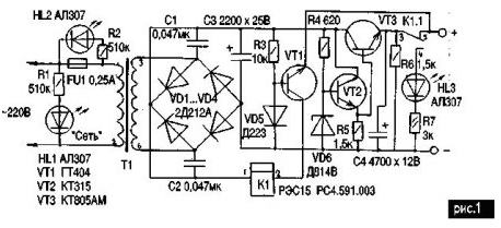
The scheme shown in Fig.1, not only indicates fault, absolutely not affecting on the output impedance of the device, but automatically disconnects the load when shorted output. In addition, the led HL1 recalls that the device included in the network, and HL2 lights up when blown fuse FU1, pointing to the need for its replacement.

Consider the operation of the device. AC voltage taken from the secondary winding of T1 is rectified by diodes VD1...VD4, collected in a bridge circuit. Capacitors C1 and C2 prevent the penetration of the network of high frequency interference, and the oxide capacitor C3 smoothes the ripple the voltage received at the input of the compensation stabilizer collected on VD6, VT2, VT3 and providing at the output a stable voltage of 9 V. the Voltage stabilization can be changed, selecting a Zener diode VD6, for example, when it XA will be 5 In, when DA - 6, DB - 8, when DG - 10 V, when DD - 12 V. If desired, the output voltage can be done with an adjustable, for this purpose between the anode and cathode VD6 include a variable resistor 3-5 ohms, and base VT2 is connected to the engine of this resistor.
Let us consider the operation of the protective device. The node short circuit protection in load consists of germanium n-p-n transistor VT1, electromagnetic relays K1, resistor R3 and diode VD5. Last in this case performs the function of stabistor, support on the basis of a constant voltage VT1 about 0.6 - 0.7 V relative to General.
In normal mode regulator transistor node protection is securely closed, so as the voltage at its base relative to the emitter is negative. When the occurrence of a short circuit, the emitter VT1, and the emitter of the regulating VT3, it turns out connected to the common negative wire of the rectifier. In other words, the voltage at its base relative to the emitter becomes positive, resulting VT1 open, triggered K1 and their contacts disconnects the load, glows led HL3. After elimination of the short-circuit offset voltage to the emitter transition VT1 again becomes negative and it is closed, the relay K1 is de-energized, connecting the load to the output of the stabilizer.
Details. Electromagnetic relay any smaller voltage. In any case, must be respected one precondition: the secondary winding T1 should generate a voltage equal to the sum of voltage stabilization and the operation of the relay, i.e. if the voltage stabilization, as in this case 9, a Ucpa6 relay 6, the secondary winding must be at least 15, but not to exceed the maximum collector-emitter transistor used. As T1 on the experimental sample, the author used a TCE-L.
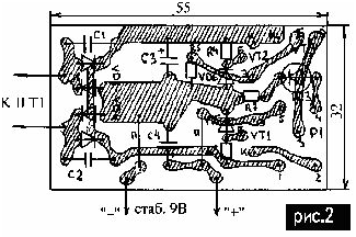
The printed circuit Board of the device depicted in Fig.2.

Literature
Author: S. V. Prus, Starokostiantyniv, Khmelnytska oblast


