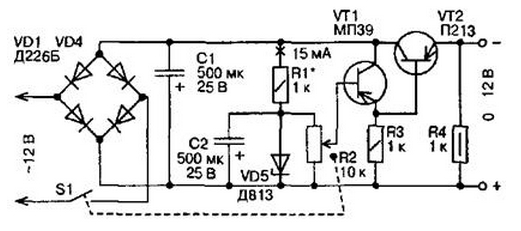
The power unit operates from AC voltage of 12 V. the Rectifier unit power form the diodes VD1...VD4 included in a bridge circuit, and the stabilizer the rectified voltage of the capacitors C1, C2, a Zener diode VD5 and transistors VT1 and VT2. The output voltage of the power supply in the range from 0 to 12 To regulate the variable resistor R2. The greatest current delivered from the power supply to the load (up to 300 mA), limited permissible direct current of the rectifier diodes.

In the rectifier you can use diodes D226 or D7 with any letter index. Variable resistor R2 to the power circuit, preferably of the group And that its the scale on which sets the output voltage of the power supply that was a uniform. In the stabilizer instead of the transistor MP39 you can use transistors MP...MP42, and instead P transistors P...P, P, with A4 any alphabetic indices. The gain of the transistors should not be less than 15.
Zener D can be replaced by a Zener D, DG or DT. The highest voltage on the power supply output will correspond to the voltage stabilization used in the block of the Zener diode. The scale of the resistor R2 should to calibrate according to an exemplary voltmeter connected to the output terminals block.
Author: A. P. Seman


