In motherboards desktop computers often use Nickel-cadmium batteries, consisting of three disc elements. When the computer is off, the battery powers the system clock and chip SHOP, containing the internal setup of the computer. Over time, Nickel-cadmium the battery becomes unusable. When you turn off the computer for more than a few hours the battery is discharged so that the system clock starts strongly to keep up, get off the installation in the chip SHOP.
Unfortunately, it is very difficult to buy a new battery - computer firms usually do not sell them. For motherboard can accommodate the battery from the phone, but the battery may cost more than similar motherboard! Be used to build a new battery domestic disc batteries D-0.06 and other impractical because their electrodes quickly oxidize and break contacts between cells in the battery.
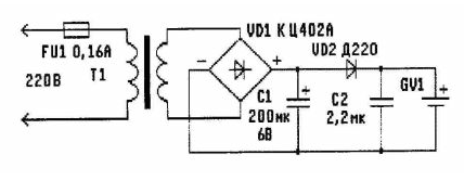
The old battery can "revive" using simple network block voltage (see figure). It will take much less time than searching a new battery.

The power supply works as follows. Mains voltage through fuse FU1 is supplied to the primary winding of the transformer T1. The transformer lowers the voltage to 3.5 V. it Further rectified by a diode bridge VD1 and served on the simplest stabilizer consisting of capacitors C1, C2 and diode VD2. The output the stabilizer is connected to the battery of the motherboard GV1. Excessive charging the battery does not occur, since the output voltage of the stabilizer (about 3.5 V) is slightly below the nominal voltage of a fully charged of the battery. Thus, the power supply, constantly plugged in, not allows the battery voltage to fall below 3.5 V. With the loss of mains voltage VD2 diode prevents battery discharge through having the leakage of the capacitor C1. The PSU is a very good "get along" with internal a charging device of the computer.
Details. Diode bridge VD1 - any of the series KTS402, KTS405, etc., the capacitor C1 is any electrolytic, for example C50-16. Diode VD2 - D, D226,
CD, etc Capacitor C2 paper or metal foil, for example K73-17 and others will be suitable for any small transformer with network the winding 220 and secondary In 3.5 V. With a little alteration you can use “personnel" transformers from old tube TVs, such as TCE-110-LM- or TCE-110-L1. Such a transformer measure the resistance of all windings. The winding with the highest resistance is carefully connected to the network. If the transformer hums and does not heat, it is suitable to work.
Measure the voltage across all of the secondary windings. If you do not find yourself winding with the desired voltage, then the frame of the transformer is wound any isolated wire test coil containing 30 to 40 turns. Often this can be done even without disassembly of the magnetic circuit. Measure the voltage across the test coil and counting the number of turns of the secondary winding based on the fact that the voltage in proportion to the number of turns. The magnetic core is disassembled, removed unnecessary winding and new wound secondary winding of the wire enamel insulation diameter of about 0.2 mm. After Assembly power supply measure the output voltage. In case you need it you can slightly reduce by including in series with the diode VD2 another diode.
Parts of the device are mounted inside a computer power supply (if place) or in a separate metal enclosure, located inside the system block. Metal casing preferably plastic from the point of view fire safety, as the PSU is plugged in constantly, without supervision.
Author: S. L. Oak, St. Petersburg


