


")

As a regulated source can be used chip CRE (analog - LM317) - at load current of up to 2A; or LT1083/84/85 at currents up to 7/5/3A; or stabilizer on discrete components.
The capacitance of the capacitor C3 is select a rate of 2000 μf 1 And the output current.
Resistor R9 is used as a current sensor for ammeter, and can be at different voltages. Usually such a resistor included at the output of the stabilizer, and increases its output resistance. To avoid this, a resistor connected to the input the stabilizer. Measurement error is very small, and equal to its own the current consumption of the regulator circuit.
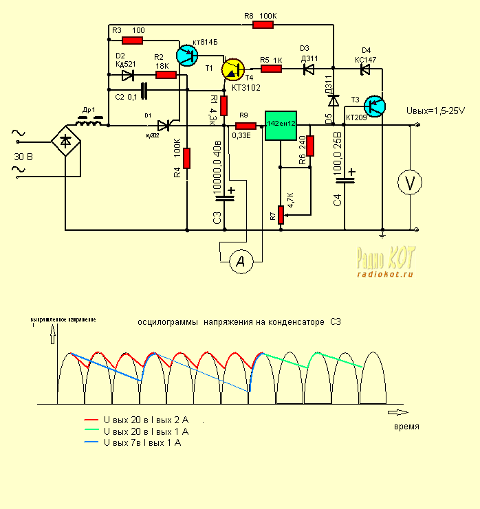
All other elements - preregulator the voltage appearing on the stabilizer. Its function is maintaining voltage difference between input and output is approximately 5…6 In (see waveforms in the diagram).
In fact, the thyristor skips all of the half-wave the rectified voltage, and some of them, depending on the output voltage and load current. This can significantly reduce the the power dissipated on the control element, especially at small output voltages and high currents.
The parameters of the inductor is not critical, its purpose is to reduce the amplitude of the current through the transformer when the lid of the thyristor. At currents load less than 2A can dispense with the throttle.
The prototype of the schema taken from the compilation Amateur structures of the GDR, published 20 years ago, has been repeated by me, but in the Internet and other collections of Amateur designs and missed, although the scheme is good.
If you want to find the prototype, but the description in German language and preregulator is only part of the original scheme.
Publication: www.cxem.net