Food security systems must be such as to maintain the battery charge and batteries and simultaneously to provide a fairly high current required for the instrument is functioning alarm (siren, flashing light etc.). This power supply has more power and is intended for the batteries are connected directly to its output 13.5 V. quality battery is most commonly used a car battery that ensures full autonomy of the security system. In addition, with a very high power of these the batteries are inexpensive, and therefore it is widespread.
Scheme
Voltage regulator
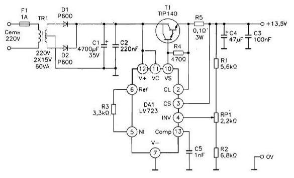
In Fig. 10.1 shows a circuit diagram of a stabilized the power source based on the chip LM723. This regulator with internal the Zener diode and Termocom-decompositions compensate current generator produces a stable the reference voltage. Output current is limited to internal transistor, responsive to the voltage drop in series with the output the resistor through which the output current flows. The maximum current output cascade LM723 chip does not exceed 150 mA. However, it is enough to control the load transistor T1, which provides a factor gain 500 when the collector current of 10 A.

Fig. 10.1. Schematic
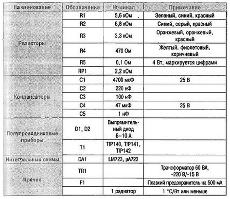
Table. 10.1. The list of elements to the scheme in Fig. 10.1

Current limit
Resistor R5 limits the current level is 5...6 A. the voltage Drop on this the resistor shifts the transition base-emitter built-in chip transistor detection and limits the output current. Therefore, when the voltage between conclusions 2 and 3 DA1 reaches the threshold value. About 0.6 V, the output voltage (pin 10 of IC LM723) decreases. The maximum value the output current corresponds to the expression:
I=0,6/R5(A).
where R5 is measured in ohms.
Voltage regulation
Operational amplifier included in the LM723, provides high the stability of the output voltage. The reference voltage 7,15 In with 6 output DA1 is supplied to the non-inverting input of the amplifier. With regard to an inverting input, it is supplied with a voltage divider R1RP1R2 proportional to the output voltage, Therefore, any change to the stabilized voltage immediately compensated by correction of the output voltage of the operational amplifier, the main function of which is to maintain a zero differential voltages on the differential input. The regulated output voltage depends on the source of the reference voltage 7,15 V. Final adjustment the output voltage is performed by using the variable resistor RP1. Capacitors C1, C2, C3 and C4 serve as a filter and power supply decoupling.
Manufacturer
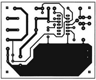
In Fig. 10.2 is a diagram of the conductive tracks of the circuit Board. Width tracks of great importance, and should be tinned, melting solder soldering iron.

Fig. 10.2. Drawing of the PCB from the conductors
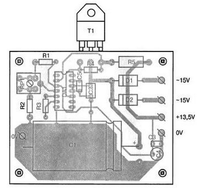
All schema elements listed in table. 10.1, with the exception of the transformer soldered to the PCB (see Fig. 10.3). Diodes D1, D2 or solder with a gap in the printed circuit Board, or replace the diode bridge, if the secondary winding of the transformer has no drainage from the middle. In this case a diode bridge or fixed to the metal case of the power module, or brazed to the petals of the transformer.

Fig. 10.3. The arrangement of elements on a printed circuit Board
The transistor T1 is set at a sufficiently powerful radiator, guaranteeing thermal resistance 1.2°C/W in direct mounting on the radiator and 1°C/W, if the transistor is isolated from the heat sink strip of mica. All cases silicone lubricant improves heat transfer.
When using a stabilized power supply in "floating" mode connected in parallel to the output of the 12V battery output voltage tune in to 13.5 V. the Floating voltage is within the range of 2.2...at 2.25 In one section, therefore, for a car battery of six sections it still 13,2 13,5...In that guarantees a full battery charge, if necessary connected to the inputs 12 In different modules.
Author: Called Kadino E.


