A tempting idea to get rid of bulky and very heavy power the transformer in the power supply of the power amplifier of the transmitter, the long-puzzling ham radio. Especially, this idea is attractive to participants radioactive, where each extra pounds of weight equipment there "own the hump".
In various Amateur radio publications of previous years were published designs transformerless power supplies. But, as a rule, were devices relatively low power intended to supply power 100...400 watts, in addition, require protection from the "wrong" enable plug in the power.
The use of modern compact electrolytic capacitors allows to design and manufacture high-voltage power pack small size and weight. This PSU is designed for amplifier power on the lamp GU-43B connected in the circuit with common cathode output power of 1.5 kW (sum - 3 kW). Using the lamp according to the scheme with common cathode, at a given power circuit, the input signal to the control grid is fed through RF transformer, and nothing else.
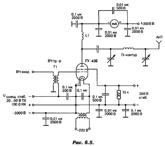
If the alarm is activated simply through the condenser, due to the fact that the output the driver circuit is galvanically connected with his case, on the net will get the variable component of the mains 50 Hz. Besides, it would result in a violation the operation mode of the power amplifier. But in the networks where the control grid connected to the cathode, such the problem does not occur. Some features of the principal scheme of such power amplifier with a transformerless power supply shown in Fig. 6.5.

The production method does not require the inclusion of additional protection from the "wrong" network connection (random rotation of the plug when can be confused "phase" and "zero"), because there is no galvanic connection power circuits with the case (in the full-wave multipliers and she unacceptable!). However, it should again be recalled that this power supply produces high stress, life-threatening.
According to the safety regulations of the transceiver must be securely connected with a proper grounding. For personal safety and the safety of others working with high voltage power supply should be very prudently, and they can only be experienced and prepared radio Amateurs. This power supply is a transformerless tenfold multiplier-rectifier voltage.
When mains voltage AC 230 V DC output the voltage is 32...40 V without load and 3000 In with a load of 1 A. Consumed by the load power is 3 kW. When tested as load used a set of powerful resistors with a total resistance of 3 ohms and a total capacity of 3 kW. This power can be consumed from the power supply rather for a long time without fear of overheating of its parts (for example, work in FM mode). When operating in SSB or CW drawdown of the supply voltage has significantly less and depends on the peak factor of the SSB signal or duty cycle Telegraph parcels. The total mass of the power unit is 5.8 kg much smaller than the mass of a similar transformer block.
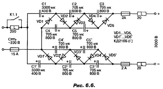
The multiplier circuit is symmetrical, full-wave (Fig. 6.6).

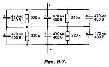
Each arm provides a five-fold multiplication of the voltage. To avoid trouble, operating voltage capacitors used must be selected with sufficient a stock. Each capacitor except C1 and C1', consists of six capacitors in series-parallel, shunt resistors (Fig. 6.7).

All capacitors that make up the container, 470 μf each. Shunt resistors applied dvuhmestnye, 220 ohms. Rectifier diodes designed for reverse voltage not less than 800 V and operating current of at least 7 A.
The inclusion of the power unit (see Fig. 6.6), is performed in two steps. First the voltage is fed through restrictive 50-watt resistor 200 Ohm, then, after 5...10 seconds, it closes the contacts of relay K1.1 to avoid erroneous inclusion in the bypass limiting resistor, instead of the relay or in important never to use any manual switches or toggle switches. Operation of the relay provides a simple scheme for self-holding, creating the necessary the delay (not shown). Shutdown can be performed in reverse the procedure or immediately. Mains voltage is fed through a fuse or circuit breaker on the actuating current of 15 A. To protect against any unforeseen circumstances, such as internal breakdown of the lamp, etc., between power supply and load a high voltage fuses 2 A and constantly enabled restrictive 50-watt resistors 20...30 Ohm.
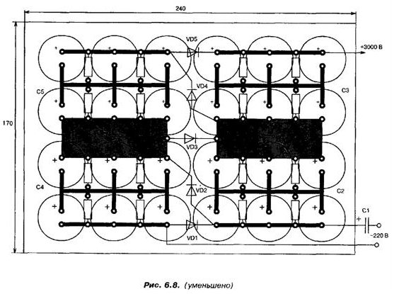
All capacitors, except for C1 and C1', diodes and shunt resistors are placed on two PCBs from foil fiberglass, 2 mm thick. Moreover, each arm of the multiplier is collected on a separate Board. In Fig. 6.8 presents one of the boards, on the other, the same Board that is reverse the polarity of the capacitors and diodes.

The size of each Board 240x170 mm. Wirings on the boards duplicated (soldered) thick stranded wire. Electrolytic capacitors, which are typed C2 C5... (C2'...C5'), used by 470 µf 400 V. They have an external diameter of 35 mm and a height of 50 mm Between the boards are connected using the ceramic struts, installation inside. On the chassis of the amplifier capacitor unit is mounted on an insulating plate made of thick PTFE.
The capacitors C1 and C1' 3300 µf, 400 V must be well isolated from the body and installed separately. (Remember that we are dealing with high voltage 3000 In - here quality insulation is important above all!). In power amplifiers categorically do not allow galvanic connection of the supply chains and the housing.
Author: A. P. Seman


