The laptop, although it is a laptop, but for the most part he is powered from the mains through an external pulse source. In this you mean, after buying the laptop I was getting a little frustrated. I naively was hoping that we can count on "Autonomous navigation" hours not less than five or six. But really, in simple text (without connected peripheral devices without using DVD-RW) only a couple of hours! It very little and absolutely does not suit me, so I decide to power up the laptop from the electrical system of the boat or vehicle (nominal 12V). But here, "slingshot", - the voltage was 18 In that won't fit.
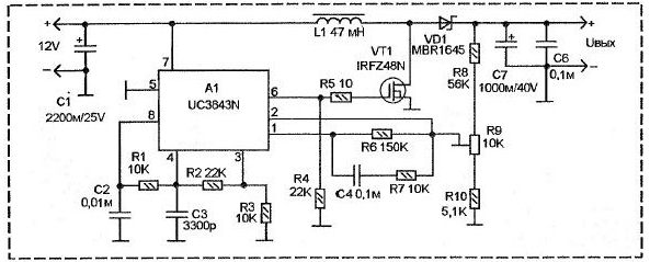
Had to do the boosting DC-DC Converter. The figure shows the scheme this Converter. I note that he has a large stock on power, since the maximum output current And more than 8, while for power laptop required no more than 3 A. can adjust the output voltage from 16 to 35 In allows you to use it for food and other apparatus for example, a laptop with a different constant voltage, or some messenger equipment. You can even feed him the car ULF, which requires the increased supply voltage.

The Converter is made on the chip UC3843 for almost the standard scheme. This IC designed to work in such circuits. It contains a generator with serotonine modulation scheme and a comparator for system stabilization the output voltage. UC3843 itself is quite powerful, but here it umoney additional output switch FET VT1 type IRFZ48N. It allowed to reduce the temperature of the device, since the transistor VT1 dissipates less power, thanks to its low open resistance and at the same time to increase the output current, limiting the symbolic radiators for A1 and VT1.
Pumping voltage occurs on the inductor L1 and rectified by the diode VD1. The sensor output voltage necessary for the operation of the stabilizer is the divider resistors R8 - R10. By means of trimmer resistor R9 set the required output voltage.
Theoretically, this scheme allows you to set the output voltage and lower at the level of the input. But really, it just turns off, and the voltage source flows to the output through L1, so no stabilization in such the case will not be.
The inductor L1 is wound on a ferrite ring C-26, it contains 25 accurately the laid winding turns of wire with a diameter of 0.47 mm folded into three sections. Can to use a single wire 1.5 mm, but reel it is not so simple.
Author: Gorchuk N. In.


