Many motorists among other tools carry with them a cheap multimeter type M, or keep it in the garage. The device is of course very useful, especially if the way something has broken from electricians, but he, although portable, but more ideal for home storage.
Especially suffers from a 9-volt battery, after which drop from the strong frost, heated to a temperature of the stove cars glove box loses significant share capacity. And the device needs such that at any moment I was ready to work. Here comes the idea to supply power to the multimeter from the "cigarette lighter" as a portable a lamp.
Of course, it can a regulator to lower the voltage to 9 V and to connect instead of "Crown". But if we are going to do measurements in circuits the machine, that is, in the circuits of the power source, the reading would be unpredictable. Yes, and the multimeter can spoil such treatment. It turns out that the power source of the multimeter must be galvanically isolated from the electrical circuits of the vehicle. This can be done using the pulse scheme Converter with an intermediate transformer.
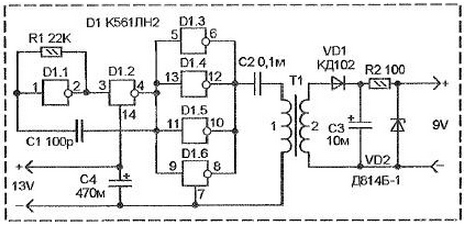
Since the current which is consumed by the multimeter is very small, then the source can be low-power. The figure shows the source circuit based on a CMOS chip K561LN2 In this chip six inverters with outputs high power. On it is made specifying the pulse generator of the pulse frequency of about 100 kHz and output buffer amp.

The master oscillator is built on the elements of D1.1 and D1.2 scheme of the multivibrator.
The oscillation frequency is set chain C1-R1. The remaining four inverter collected in parallel and constitute the output buffer stage.
Parallel connection of elements allows to obtain increased power to output. Pulses from outputs connected together D13-D16 come through the coupling capacitor C2 to the primary winding of the RF transformer T1. With the secondary winding of the AC voltage supplied to rectifier VD1-C3 and parametric stabilizer R2-VD2 that support the output voltage at 9 V.
The transformer T1 is wound on a ferrite ring size ferrite him 2000NM. Pre-swim-up ring to smooth out fine sandpaper so they are not destroyed winding insulation. Then the ring is to coat a thin layer of epoxy the lacquer. And after drying to wind two coils. The primary contains 30 turns, the secondary winding 60, both windings are wound wire sew 0,12 (or so). The windings are located on opposite sides of the ring.
Chip K561LN2. You can replace foreign counterparts CD4049, but it's not full analogue as it is in a 16-pin package and is different Pinout. Generally, you can use a chip with four inverters, for example, KLA, two of them to let multivibrator, and two on the buffer, but what will be the results of the output current will be clear from the experiment.
Diode CD can be replaced by CD, KD522, 1N4148. A Zener diode. DB-1 - the glass body.
Here you can apply any of the Zener voltage of about 9 V.
The output current of the Converter is 8.9 mA. this is enough to power the multimeter type M.
Author: Snegirev I.


