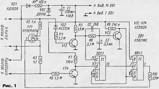
The proposed device is another electronic means of preventing unauthorized use of a telephone line. Its scheme is shown in Fig. 1.

In the initial state when the inputs R triggers DD1.1, DD1.2 high logic level, on the straight there is a low outputs.
When removing the handset master apparatus or a "pirate" connected to line up resistor R3, the voltage on the line drops, closes the transistor VT2, opens VT3 and the inputs R of the flip-flops are set low. However switch trigger will not occur and the line will remain desabla-kiravani. Moreover, if the tube was removed "pirate", then the current through the resistor R3 and not leaking the input D of the flip-flop DD1.1 is kept high level.
When dialing a "pirate" at the entrance With DD1.1 receives pulses which rewrite information from the D input to the flip-flop output. As a result the output trigger DD1.2 set high level. Transistor VT1 will shunt line, and dialing will become impossible.
When the number is dialed, the owner of the phone, at the time of contact closure dialer due to the current through the resistor R3, the transistor VT4 opens. With a small delay (due to the capacitor C2) to the input With DD1 comes positive the voltage drop. Both triggers remain in the initial state and the blocking the line does not occur.
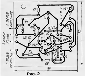
The device is assembled on a printed circuit Board (Fig. 2).

The power of the device can be made from the telephone line (as shown in scheme) or from a separate source.
With proper Assembly of the device does not require networking. It is not critical to the accuracy of the values of resistors used, except for R1 which defines the level of the supply voltage and affects the amount of current consumption.
Author: B. Porography, Krasnoyarsk


