Now, with dominance of mobile and cordless phones, landline phones become "irrelevant" and often simply discarded But them. making a small revision, can be successfully used for simple communication devices. One such communication devices (for two users), even a novice ham, covered in this article.
Functional diagram of a wired telephone apparatus shown in Fig.1 [1].
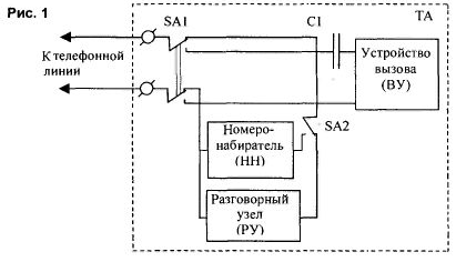
When hang up a telephone pine are connected to the calling device (WU) through the switch SA1 and the coupling capacitor C1. which passes only the variable component of the ringing signal. When you lift the handset. SA1 switches in the upper position (as shown in Fig.1), connecting line with spoken node (PN). Dialer (NN) is connected to the line through the switch SA2. At the time of dialing this switch disables spoken node. Because two subscribers dialer is not needed, it is advisable that it be deleted.
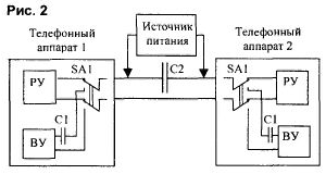
When designing two-wire intercom system of power is most often carried out as shown on Fig.2, (source connected in series with the telephone sets, and a capacitor C2 bypasses it for speech signal). In the case of stable power source the role of C2 performs the output filter capacitor. In this the constant voltage circuit in the line does not change. But the caller must be the signal generator call disconnected when removing the second subscriber of the tube. The second disadvantage: if the power supply is on the called party and not enabled, communication is impossible.
In telephone networks (urban PBX) power line is parallel (simplistically shown in Fig.3). The line voltage Il is defined as Up=UистUr. It is about 12 when it is removed In the tube, which ensures the normal operation electronics (electronic devices).
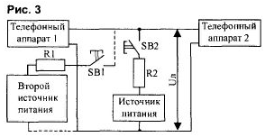
The advantage of this system is the nutrition. that it can be included in parallel with either side (shown by a dotted line in Fig.3). In these telephone networks call the signal is formed on the PBX and is sent to the line. This DC voltage in the line remains at the level of a stage. When the called party answers the call (to the line connects spoken node), line voltage Il decreases (below 20 In) that is a command PBX to disable ringing signal. As can be seen, parallel circuits, eliminating the problem of supply leaves unresolved the issue of generator call.
In the proposed device the call signal is formed on the called party. For in the device of the call at the receiving side is provided a generator that responds to the reduced voltage. This decision not only significantly simplifies the circuitry, but also allows to disable the call generator. Replacing the handset (Fig. 1) setting up a call, the call generator, get that when lifting tube SA1 will shut off the generator, and its signal will not fall in line. Control signal to trigger the call generator is reduced of line voltage up to 20...15 V, which is provided by simple removal of the tube on to the caller. Alteration of the phone is to replace the calling device, leaving conversational node without change, regardless of the type of telephone of the apparatus.
Diagram of a communication device depicted in Fig.4. It works as . MocrVDI simplifies the connection of the phone line: no need to comply with the polarity. The line voltage is supplied through the divider R3-R4 to the input circuit DD1. The divisor is chosen from the condition that when the voltage level IIS the entrance DD1.1 correspond to a logical", and lowering the voltage to 20 V - "0". In this case, the divider must have the highest possible resistance, so as not to shunt the line. A logical "0" input element DD1.1 leads to the "1" appears at its output and at the output of DD1.3 (DD1.2 and DD1.3 double-invert signal), and the output DD1.4 - "0". The low level output from the DD1.4 closes the transistor VT3, and the high, the output of DD1.3, opens the transistor VT1 and, accordingly, VT2.
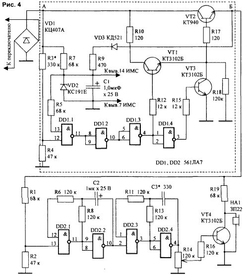
Using the public key to VT2 voltage is supplied to the ringing signal generator on the chip DD2. Generator-dual tone. On the first two elements (DD2.1 and DD2.2) is assembled low-frequency oscillator, the second two (DD2.3 and DD2.4) - high. The load of the generator is the key on the transistor VT4, the output of which included piezo oscillator HA1. The power IC with private key provides VT2 chain R7-VD2-C1. and when you open (because the current consumption increases due to the generator DD2) - VD3-R9-VD2-C1.
Described refinement refers to simple phones without electronics. When the alteration of such devices is a coupling capacitor and a call turn on the device. The piezo oscillator as new Board, be located in any convenient place in the body of the phone. For devices with electronic calling devices (for example, on a chip CRUZ) enough to make only a part of the proposed scheme (Fig.4 circled the dotted line). The generator and the emitter of sound are those that are already there is a remake in the apparatus.
Although the basis for negotiation of the device taken PABX system, it makes no sense to ask voltage of 60 V. For such a device is sufficient At 30 V. phones with "electronic stuffing" it is important to ensure that the line, loaded at one phone was given voltage within 14-18, and two 10...14 V. This provides normal (without distortion) spoken work site. If desired to reduce the power consumption can be connected to a second power source (as it is shown in Fig.3). In this case, the caller includes a source power, but there is one disadvantage: when connecting lines should be observed polarity to accidental simultaneous operation of both sources, they are not was the United counter. To do this with both sides of the line can be enabled the LEDs. If you use a modern super-bright, enough current 2...3 mA, which will not affect the operation of the circuit.
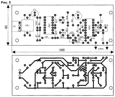
The device is assembled on a circuit Board of one-sided glass fiberglass thickness of 1.5...2 mm and a size 100x40 mm the Drawing Board is shown in Fig.5.
The diagram of the power supply depicted in Fig.6. It needs to provide the desired voltage (in my case - 30 V) and a current consumption of at least 100 mA. Second requirement - minimum ripple at the output, as in the phones very well audible background 100 Hz. Instead of the ballast resistor is used miniature light bulb (26 V, 0.12 A). It is disabled when both the apparatus of the lamp is not lit at all, when one (during a call) - dim, when the conversation vividly.

Details. Transformer-model, TA-1 or TA-2, but any that provide the voltage on the secondary winding 35.. .40 V and a current of at least 100 mA. Permanent the resistors in the device - MLT-0.25, variables - GPA-22. The electrolytic capacitors - type K50-35 or foreign counterparts, constant - km, KD or their analogues. The transistors can be replaced CTB any other low-power n-p-n structure with allowable voltage the collector-emitter of at least 45 IN, CTA is replaced by CT, CT, etc.
A diode bridge is any. You can assemble the bridge and from the individual diodes KD521 or KD522. The Zener diode VD2 is selected with a small current stabilization - XE. The piezo oscillator SP can be replaced with UR1 or SP. Instead DD1 CLA you can take CLA (without any modifications) or K561LN2, but R3 you should exclude and take into account the change of the Pinout. DD2 can be replaced by CLA. You can also use their analogs series 176. If it is assumed persistent use of the device, the IC stabilizer should KREN set on a small radiator
Structurally, the device is performed in a separate module and is the telephone in any convenient place. In older phones (with electromagnetic bell) sound projector can be placed under the holder the tube or on the back wall, and a fee - in place of the call. In phones with electronics emitter is worth it, the Board itself is small (no generator), so it can easily fit even in phones-tubes. Power source runs in a separate unit, it can be located as one of the devices, and anywhere along the telephone line.
Before commissioning the device controller R4 power supply voltage is set output (UMCT). A load is connected. Selected resistance R3 (Fig.4) to provide "1 * at pin 11 DD1 removed when the tube (voltage in lines below 20 In) and "0" at a position (in the line - UMCI). Selected capacity C3 to ensure the desired timbre and volume. The length of the line, experimentally verified by me, was in excess of 300 m. the Loss of quality is not was observed.
Literature
Author: G. Sauridi, Ryazan


