


")

The article focuses on the use of the DTMF receiver in CT as a narrowband detector single-tone sinusoidal signal in the range of sound frequencies up to 5 kHz. The device has a high characteristics.
In Amateur and professional practice, often have to solve the tasks of the narrow-band filter low frequency signals with their subsequent detection and digital processing to determine the membership of a signal to a particular frequency or group of frequencies. An example of this can serve as receivers DTMF signals, widely used in telephony (dial in tone mode) and in radio (personal radio-call).
Usually for the identification of sinusoidal signals in telephony, remote control used analog filters (active or passive), tune the desired frequency. The received signal is detected, is supplied to the comparator, which is already removed logic signal the presence or absence of a tone of a given frequency. Such detectors are rather cumbersome and do not always satisfy the requirements stability in frequency with changes in temperature and supply voltage.
With the advent of technology manufacturing filters of the switched capacitor (switched capacitor technology SCT) the challenge of achieving high and stable characteristics of filters is greatly simplified. Many foreign firms produce different types of filters, made by this technology. For example, MAXIM company produces a wide range of integrated active bandpass and notch filters, filters for bass and treble with the characteristics Chebyshev. Butterworth, Bessel, Gauss different orders (2 to 9), which you can program the center frequency/cutoff frequency from a few tenths of a Hertz up to 100…200 kHz and the quality factor from 0.5 to 64 by means of jumpers or under microprocessor control.
This versatility, of course, can not affect the price of these products. The cost of their domestic dealers high enough to purchase them is not always simple, and the use of the detector of single-tone signals requires, as noted above, the detection and further digital processing.
In this case, it seems interesting application of well-proven in telephony and radio systems receiver DTMF signals KT SAMSUNG (analog MV8870 firm GEC PLESSEY SEMICONDUCTOR). Domestic analogue is KT3170 Mick roshima CRUZ production of the Minsk production Association "Integral".
This receiver decodes the 16 standard tone pairs into a 4-bit code. Made on CMOS technology using bandpass filters on switchable capacitors it has the following characteristics:
- narrow bandwidth (1.5% of center frequency);
- wide dynamic range input signal (from 77 mV to 2.45 In);
- high impedance analog inputs IN+/IN -- 10 MW (typical the value at 1 kHz);
- low power 15 mW;
- high frequency stability of the parameters over a wide temperature range (from -40°C to +85°C).
However, the receiver decodes only a pair of standard DTMF frequencies of the upper and lower frequency bands determined by the frequency of the master oscillator (standard value - 3,58 MHz). and does not respond to single tones.
The principle of decoding a single-frequency signal shown in the block diagram (Fig. 1).
Since the DTMF receiver decodes only a pair of frequencies, it is necessary at its input to the investigated single-tone signal having a frequency Fc to add the exemplary frequency F0, complementary to the standard pair. Therefore, the input of the DTMF receiver submitted by bitonal signal, which is decoded in the usual way.
As a generator of reference signal it is convenient to use the DTMF generator TR (TR) having a mode of generation of single-tone signal. As sync DTMF receiver and generator is provided by a single internal crystal oscillator, standard pairs are formed automatically.
Consider the schematic diagram of the device on the example of the detector Fax signal (Fig. 2).
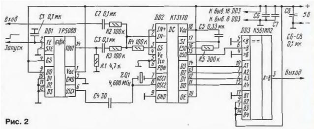
The detector shall operate on the presence in the communication line signal a frequency of 1100±15 Hz with a duration of 0.5, which is transmitted geeky Fax machine when establishing a connection for Fax transmissions data.
The DTMF receiver DD2 included in the model scheme. Operational amplifier, built-in the chip receiver included as summing the transmission ratio is equal to 1. The input impedance for the signal under investigation is determined by the resistance resistor R2 and is 100 ohms. The clock frequency is stabilized quartz resonator ZQ1. Clock pulses are also supplied to the receiver and DD2 to the generator DD1.
Vimasuma chain C5R5. connected to the output ESO, serves to protect against possible interference, including speech, providing temporal filtering of the signal. With its help, it will test the duration of the received signal. The signal duration is less than the specified are ignored. It also checks in the presence of a valid character pause. In other words, the chip will not be to accept DTMF signals shorter than the valid duration, and will not be considered loss of valid signal is shorter pause. When specified on the diagram the values of this time is 80… 100 MS.
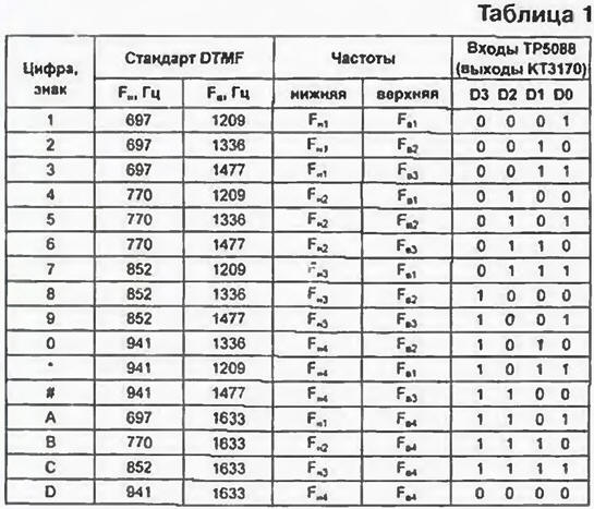
Chip TR company National Semiconductor is a DTMF generator signals running on the microcontroller. At its inputs DO - D3 (findings 9 - 12) serves the binary equivalent of the numbers, characters or letters (PL. 1).
When the input (pin 2) low, DD1 chip is microparasite and on the TOUT output (pin 14) no signal. When you change level at the input of THOSE with low to high, the data inputs D0-D3 are stored in the register of the chip, the internal oscillator runs (if it has its own frameshadow chain). The signal selected tonal pairs of standard DTMF frequency appears at the output TOUT and is present as long as the input THOSE will not appear again the low level. The TOUT output pin is open emitter. Time diagram of the generator and the parameters of the signals shown in Fig. 3.
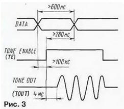
Capacitor C1 is mounted on THE entrance, in conjunction with an internal resistor chips form a trigger circuit of the generator when the power supply. It set if use tone decoder standalone (without micro-computers).
The entrance STE (pin 3) controls the generation of one or a pair of tones. When he connected to the positive output of the power source or connected to nowhere, generated a pair of tones. In our case, this input is connected to GND for generating a single tone. The input signal GS (pin 4) defines the generation of a single-tone signal from the upper or lower frequency group (tab. 1). With a low level on this input signal is generated with a frequency of the lower groups at high (or disabled) from the top.
We now give a method of calculating the frequency of the master oscillator, which determines the frequency of generation of single-tone signal and, as a consequence, the tuning frequency the tone decoder. For this we define the division factor of clock frequency accordingly, for each tone frequency standard DTMF signal empirical formula: k=FH/Fг or k = FB/Fn where Fn is the frequency of the lower band in Hertz. FB is the frequency of the upper band in Hertz. Fг - specifies the frequency generator in megahertz. The calculation of coefficients to produce a standard The DTMF frequencies, i.e. when the frequency of the master oscillator 3,579545 MHz (3,58 MHz). The results of the calculation are presented in table. 2.
Next to the desired frequency of the tone decoder 1100 Hz the estimated frequency the master oscillator Fr for each according to the formulas given above, and choose quartz resonator frequency that is closest to the calculated (tab. 2. column 4). In this case, it is the common frequency of the resonator 4.608 MHz. Based on this calculated frequency by the same formula (tab. 2, column 5).
As can be seen from table 2, the initial frequency of the tone decoder 1100 Hz (calculated 1097 Hz) corresponds to the frequency Ft0 from the lower group. Now if as auxiliary frequencies to choose any of the top group, for example, FB1=1557 Hz. and use the truth table of the DTMF receiver and generator (see tab. 1), you can define a binary code. required at the input of the DTMF generator to obtain the signal frequency 1557 Hz, and the code read from the outputs The DTMF receiver. corresponding to the input signal having a frequency of 1100 Hz.
The generator will produce a signal frequency 1557 Hz when applied to its inputs binary code corresponding to all symbols of tonal frequencies which have the frequency Fв1 namely: "1", "4". "7", this, of course, to the input of the GS chip DDI must be submitted to the high logic level. In the diagram (see Fig. 2) shows filing code corresponding to the numeral" 1". Code at the output of the DTMF receiver to correspond to the number "7" (voice frequency Fи3 and Fи1).
It is quite obvious that one receiver can define up to four single-tone signals. In this example, signals with frequencies 899, 991, 1097 (our the Fax signal) and 1212 Hz. The identification of these four signals is based on code read from outputs DD2 in the presence of a gate signal at the output DSO (pin 15). which appears every time the receiver detects one of these frequencies. If it is known that the channel may be present only one frequency, as the output of the tone decoder is permissible to use just a DSO.
It should be noted that the algorithm of digital signal processing provides protection from reception accidentally coincident signals, in particular speech, and also at there are more than two signal frequencies. This feature should be taken into account.
For standalone devices, i.e. not running microcontroller or the computer. as a generator it is also possible to use chip TR. having inputs for connecting a 4x4 matrix keyboard. Closing the relevant conclusions of columns and rows each other or to a common wire, making the generation of single-tone signal required frequency.
Options for building decoding nodes shown in Fig. 4.
Because data on the receiver output DD2 recorded in the register latch and remain in it after alarm actions DSO, decoders must Gating signal DSO.
The maximum frequency of the master oscillator, which are stable these chips, is 9-10 MHz. Therefore, the maximum frequency, detected by the receiver, is in the range of 4100 ..4560 Hz.
Author: O. Potapenko, Rostov-on-don