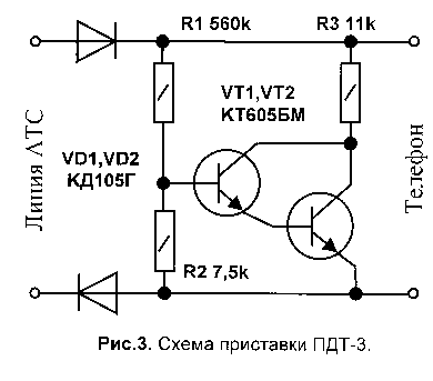
Immediately say, that not to be confused paired the inclusion of THE parallel.
It is known that on a phone lines coupled to enable THE apply consoles diode separation of circuits that established themselves in the vicinity subscribers (usually guards the landing). Their the schematic diagrams shown in the figures below. The principle of operation consoles diode separation based on the block chain power is not working in this the time TA and simultaneously ensuring the supply of operating THE same. It by the incorporation of linear chain of handsets a blocking diode in polarity, opposite for one and for another TA.
In addition, to ensure normal operation polarized calls telephones, set-top boxes equipped with a discharge circuit for forming a second current half-wave via a call during those half-cycles ringing PBX when the blocking diodes are closed ie, the capacitor cannot be discharged through a PBX because connected diodes.
Fig.1.
Scheme prefix CTPS-1 
Fig.2.
Scheme prefix CTPS-2
Such telephone lines many drawbacks, and one of them is lowered level ringing signal. What the calling device THAT some (especially foreign) in which the scheme is designed for a rated the voltage ringing signal, when paired inclusion THAT may not to work. Not without drawbacks as well and the discharge circuit of the capacitor in the circuit call. Which in my opinion is the main reason the failure of most electronic calling devices telephone sets, because they a sufficiently high resistance compared with electro-mechanical.
Pages Amateur literature, including in The Internet, repeatedly to "pop up" this issue. Everywhere offered to install additional devices that not just complicate the connection him THAT their placement, but also lead to the weakening of the signal, and sometimes quite unworkable in real conditions. And the price some of them reach up to 10 dollars!! This is - excuse me, crazy!
Our city has several various exchanges and faced with this problem turned out to be that one and the same consoles on different exchanges are themselves in different ways. Therefore, the prefix it should be set up specifically for your PBX. Exactly about and wanted to share your considerations. And give some useful tips.
First
If you have the console CTPS-1 (Fig.1.), then it should be replaced, because it setting too time-consuming (selection transistor). In this case I recommend to remove all details (other than diodes) is removed from the console and mounted Assembly to solder on any from the model diagrams on Fig.2 or Fig.3. (I recommend Fig.3.)
Secondly
Immediately I want to make one comment. The value of the resistor R3 by the circuit Fig.3 should be increased to 24 ohms, as and by the circuit of Fig.2. Not to reduce the resistance of these resistors nige ohms, because it can to cause crashes on some exchanges. Although according to the standard scheme of its nominal 11 ohms.
I was made device, containing on a total PCB two identical consoles scheme CTPS-3. Drawing of the PCB is shown in Fig.4, and installation in Fig.5. To connect to the device of the wires on the Board a metal contact of the bracket with the bolt on the middle of the old ONE. Collected the fee is placed in a plastic the casing of suitable size. In the device was applied transistors CTA, resistors MLT-0,5, and diodes CDG, under which designed printed circuit Board. New the device was installed instead two consoles CTPS-1. In schemes CTPS-2, CTPS-3 were tested transistors CTA. In the console CTPS-2 work better KTM. Recommended resistors MLT-0,5; 0,25.
All consoles are identical and are as follows. Measure the voltage of your telephone line. Measurements produce arrow voltmeter - digital is not suitable here due to its large inertia. Further temporarily instead of the resistor R2 connect the variable resistance 20...30 kω, setting the slider in the position of minimum resistance. Now, get on the entrance consoles direct voltage, higher by 3...5V, than previously measured on the telephone line.
Connect the voltmeter to the output and consoles slowly increasing the resistance of the variable resistor follow the indications the voltmeter. You need to find the position of the slider of the variable resistor, which the voltmeter will start to decrease. Lock this position variable resistor, disconnect it and measure the resistance. And in its place, solder a DC resistor of the same value. The device still then functions normally! (Fax, modem, cordless telephone.)
Literature
"Telephones and pay phones". I. M. Gurenko, E. V. Kuchumov. Radio and Communication 1989.
Author: Y. Sachkov, Pervouralsk, Sverdlovsk region; Publication: N. Bolshakov, rf.atnn.ru


