


")

Chip KRKN is an electronic switch two parallel telephone sets. Schematic diagram of the lock of the phone shown in the figure.
Its work is carried out as follows. If you remove the handset on TA1, the thyristor in the IP will open and the phone connects to the line. The voltage drop across the thyristor chip is not more than 2 V. at the same time locks the thyristor IP in the second circuit that allows you to turn it off for a while, until the tube is in the lowered TA1.
If, at the end of the first ONE. the second tube will be removed, we will be switching apparatus on the line. Current consumption from THE line when lowered the tube should be no more than 0.4 mA, otherwise the thyristor chip na closed after the end of the conversation. During dialing, on one of the machines in the break loop line there is a short outage this phone from the line. To offhook one THAT in this interval of time did not cause the switching of phones, in the control circuit includes the capacitors C2 and C3 to delay switching phones. The capacity may be in the range of 5-10 UF.
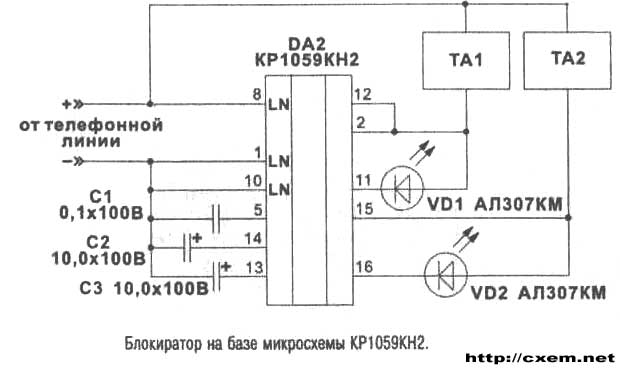
LEDs VD1 and VD2 are intended to indicate THAT in conversational mode.
When you receive a call from a PBX (70-90) call both phone.
Publication: www.cxem.net