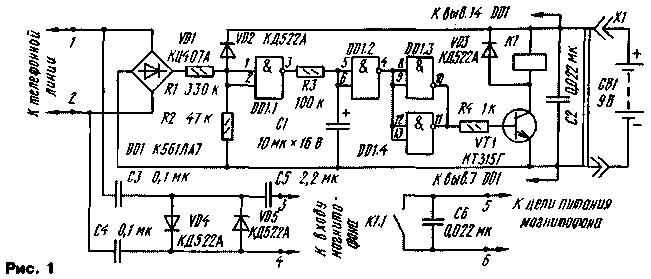
Sometimes you may need to record a phone conversation on a magnetic tape without being distracted to turn on the tape recorder. The problem will be solved if you connect the recorder with the telephone via the proposed console machine.
The described device automatically turns on the tape recorder to record the conversation, and off when on the phone. In the operation of the console-machine tape must always be included on the record. Turning on and off by means of the switching power supply circuit. Diagram of the device shown in Fig.1.

The telephone line voltage is applied to the divider resistors R1 and R2. When the handset is on the lever, the line voltage of about 60 V, the output element DD1.1 low level, the capacitor C1 is discharged, the output DD1.3 as a low level, the transistor VT1 is closed, the relay K1 is de-energized, the power to the tape recorder off.
When hook line voltage drops to 5...12 V, the output DD1.1 - high level, the capacitor C1 begins to charge through resistor R3. When the terminals of the capacitor threshold condition of the elements DD1.2 and DD1.3 is reversed, resulting in the output DD1.3 appears a high level. Transistor VT1 is opened, the relay K1 is activated. Through the normally open contacts of the relay is powered on tape. The audio frequency voltage is supplied from the line through the chain C3, C4, VD4, VD5, C5 on the line input of the tape recorder.
At the end of the conversation, as soon as the handset is put on the lever, the line voltage will increase to 60 V. the output element DD1.1 appears low. Capacitor C1 begins to discharge through the resistor element R3 and DD1.1. As the voltage on the capacitor reaches the threshold level, the elements of DD1.2 and DD1.3 will change its state. Transistor VT1 is closed, the relay contacts K1 will open and shut off the power to the recorder.
Since the time constant circuit R3C1 significantly more follow-up period series "typesetting" pulses, when lifting the handset and dialing the tape remains de-energized. However, if you pick up the phone and dial the number for some time, the capacitor C1 will have charged and will turn on the tape recorder.
Send ringtone (80...120 V, 25 Hz) also does not change the condition of DD1.2 and DD1.3. Diode VD2 limits the voltage at the input element DD1.1. The resistance of the capacitors C3 and C4 at a frequency of 25 Hz high, so they no shunt ringer. Diode VD4 and VD5 limit the voltage at the input of the tape recorder at 0.6...0.7 V.
Chip CLA interchangeable on CLE, and a similar series C and 564. Diode Assembly CCA (VD1) can be replaced by CCB, CCB or four diodes with a permissible reverse voltage of 200 V. the Transistor VT1 - patterns n-p-n with acceptable power dissipation collector not less than 150 mW. Relay K1 - on voltage 5 positives...7 In, for example, RAS (passport RS4.524.302 or 031-04-02), RES15 (passport RS4.591.003).
Parts of the device are mounted on a printed circuit Board of foiled fiberglass. The drawing shown in Fig. 2.
Establishing device is reduced to the selection of resistors R1 and R2 to provide a clear response element DD1.1 when raising and lowering the tube. But the resistance of the resistor R1 should not be less than 330 ohms. The delay time of the relay can, if necessary, change the selection of the resistor R3.
Author: Andrei Kurguzov, Moscow; Publication: N. Bolshakov, rf.atnn.ru


