


")

The indicator light phone calls can work instead of a phone call or simultaneously with it. It will be useful for elderly people the hearing impaired, and will save you from a phone "trills" at night time. The device will be necessary, if the apartment sleeps a little child.
Industrial consoles similar purpose unreasonably the road and the scheme given in the magazine "Radio" (9/1992) has a significant weaknesses: the indicator is triggered and when speaking, and when dialing, consumes electricity from the mains in standby mode, inconvenient to connect to TL.
The proposed device is devoid of these shortcomings. The article provides three options for performing such a console. All the schemes do not consume energy in standby mode, do not work when talking or dialing on THE one and long-term operation of the devices showed high reliability.
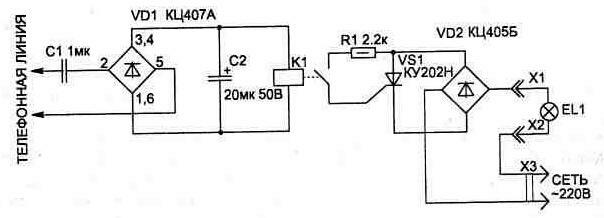
Fig. 2.6. The electrical circuit of the indicator light phone calls
The first scheme (Fig. 2.6) connects to your telephone lines at any place in parallel with the phone and has no influence on his work because of the large input resistance. If line ringing he straightens up on the element VD1 and served on reed relays with operating voltage 27 IN - RASA RS4.569.601 (RS4.569.606) or RESB RS4.569.626 (RS4.569.631), which, when activated, includes the thyristor VS1.
The scheme can still be simplified if instead of the diode bridge VD2 use one diode connected in series with the thyristor load. Then the brightness of the lamp will be reduced and the illumination will be a little pulsating (which is irrelevant), as it will only work on one the half-period of the mains voltage.
All circuit elements are placed on unilateral a printed circuit Board with dimensions h mm (see Fig. 2.7) or can connect surround mounting within the housing of the phone. The casing is installed switch S1 (see Fig. 2.8), and instead of the capacitor C1 can be used a capacitor having in the telephone call in the chain, if its capacity not less than 0.6 UF.
Fig. 2.7
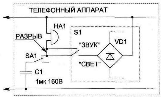
Fig. 2.8. Connection diagram led lighting up when placing it inside a phone apparatus: 1 - phone call; SA1 - switch associated with the lever the provisions of the handset.
Used in the unit capacitors: C1 - MBM or similar at 160 V; C2 - C50-6 at 50 V. the Diode matrix VD1 can be replaced on CCB, B, G, D. the Use of other types of relays are unacceptable, as they can overload the telephone line under the action of the tone.
With proper installation, adjustment is not required. The second scheme (Fig. 2.9) are collected at a neon lamp (HL1), the transistor oscillator (VT1) and the triac switch (VS1).
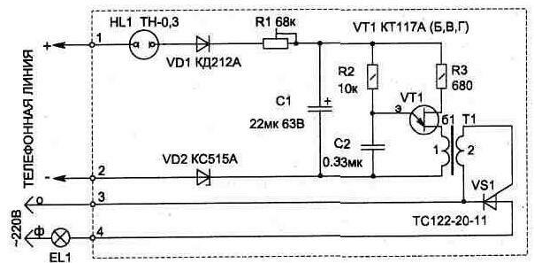
Fig. 2.9
Feature a neon lamp is the ability to pass current (in fire) when the voltage exceeds the maximum value of 90 In that allows its use as a threshold element. The amplitude of the voltage in a telephone call line exceeds this value. As HL1 can be used and other types, for example TN-0,5.
On the unijunction transistor collected oscillator forming short pulses for opening the triac switch. When wrong the polarity of the pulse arriving at the office VS1, the triac does not open (when setting up will have to swap the conclusions to one of the windings T1).
Fig.2.10
The resistor R1 allows you to adjust the sensitivity light indicator so that it did not work when dialing on your TA.
A printed circuit Board for the circuit shown in Fig. 2.10. The structural design details: capacitor C1 type K52-1B, type C2 K10-17,the resistor R1 type JS4-1, others - C2-23 to 0.5. The triac will fit any other, less powerful.
The parameters of pulse transformer T1 is similar the parameters of the transformer described in the article for the circuit in Fig. 1.17.
The third diagram (Fig. 2.11) is similar to the principle the work described above, but as a threshold element is a Zener diode VD2, and except for the light features include an audible indicator.
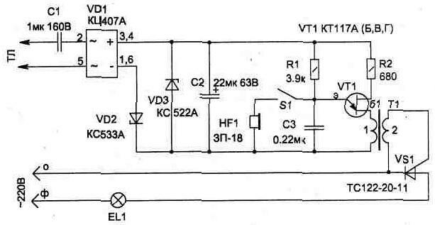
Fig.2.11
The scheme is not critical to detail and with the correct Assembly configuration is not required.
When connecting the circuits to the network 220, it is desirable to observe the phasing shown in the diagram. This will eliminate the possibility of interference penetration in the TL (at the moment of inclusion EL1) through decoupling pulse transformer T1.
Publication: www.cxem.net