In recent years in our country there are many cheap phones-handsets foreign production. They cause a lot of trouble to their owners, as fail frequently. The main reason for this is the difference of the arguments domestic and foreign exchanges. About the repair of one of the variants of such tubes told in the article.
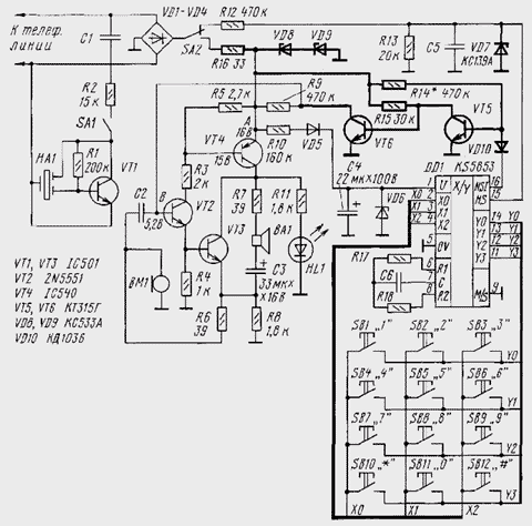
I want to share my experience of repairing phone-tube assembled on a chip KS5853. His scheme is shown in the figure. Lever switch shown in SA2 the "on-hook".

The device worked only call when hook line classes did not occur, i.e. the voltage at the emitter of the transistor VT4 was equal to the voltage telephone line. To analyze the causes of failure of the apparatus had to disconnect from the phone line and connect to DC voltage of +15 V. the Positive conclusion was connected to point a, and the negative to GND. Measurement modes all semiconductor devices revealed that the transistor VT2 is closed, as the potential of its base (point b) was practically equal to zero. There is a fault speaking of the site, assembled on the transistors VT2, VT3, VT4. It was the consequence of failure of parts of the chip DD1, conversational management node.
I vipal DD1 chip with a needle from a medical syringe and unbending 16 the stem, soldered into place. After that, it became clear that all functions of the machine recovered, except for dialing, as the signals of the set came from the 16th the pins in the base VT2.
Unplugging the receiver from the telephone line and connecting it to a power source, such as stated above, with an oscilloscope was able to establish that on the 16th DD1 output there is a noise amplitude of 2 mV. When you press any numbers on the keyboard it turned out that this conclusion is a useful signal dialing. On the screen oscilloscope it looks like alternation of noise and useful signal in the form low logic level. Upon finalization of the phone (the newly introduced elements shown with bold lines) dialing recovered. It turned out that you can do without replacing the chip on CRUG.
Resistor R14 should be selected so that the transistor VT5 be saturation when no signal is dialing in the cutoff mode, when this the signal is present at pin 16 DD1. The resistor R16 and the Zener VD8,VD9 necessary for the protection of high voltage ringing signal in the case removal of the tube during its operation. Zener same VD7 serves to protect chip, and the diode VD10 ensures reliable opening of the transistor VT5 in the absence of a useful signal.
Completion of phone-tube held mounted Assembly. Incidentally, the led HL1, signaling offhook and telephone lines were also malfunctioning. It had to be replaced by led ALBM without any alteration.
Transistors VT5, VT6 can be replaced by CTE. Diode VD10 - any silicon.
Author: A. Soldatenko, Maykop


