


")

In literature one can find descriptions of the various instruments to test and repair telephones as their connection to the PBX lines and offline. However many of them are quite complex. The author proposed development has put before a goal to create the most simple stand-alone device with a wide opportunities.
With the help of this device, without connecting to the PBX lines, to check the work Electromechanical calls and electronic calling devices phone apparatus (TA), their conversational units and dialers. The device may Autonomous test not only fully stocked disk and push button TA (including cordless), but also separately disk dialers and used on coaxial lines consoles diode separation circuits CTPS-1,CTPS-2, CTPS-C DP-1.
Diagram of the device shown in Fig. 1. It consists of three main components: simulator telephone line, generator signal "Response station" and the Registrar number pulse dialing. Mode select switch SA2. In the top (the scheme) the position of its movable contact mode "Response station", and in the lower "Verifying dialer". Have a helper mode "Test call", activated by pressing the SB2 in any of the major modes.
The line simulator consists of diodes VD1-VD4, capacitor C1, resistors R1 - R3, relay coils K1 and K2. While the tube is connected to the device THAT has not been removed, a constant voltage across its terminals is 60 V. the off-hook it drops to 5… 15 V depending on the type of TA.
Signal generator "Response station a frequency of approximately 400 Hz assembled on transistors VT1 and VT2. The frequency can be changed by selecting the value of resistor R4. This signal is sent to the output device via an isolation transformer T2. Since the voltage of the generator is fed through switch mode work SA2 and the contacts of relay K1.1, actuation of this relay when picked up tubes causes the appearance of continuous tone in the phone.
For the purpose of simplification as a ringing signal used AC voltage frequency of 50 Hz with a secondary winding of the transformer T1 is connected to THE contacts button SB2.
The Registrar of pulses set is assembled on the decimal counter with a decoder and DD1 led semielemental indicator HG1. The pulse dialing with rolling contact relay K2.1 arrive at the counting input DD1. Clicking on the button SB1 counter return to the initial zero state.
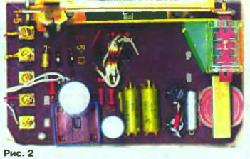
One of the variants of the device mounted on the Board from telephone set TA-68 (Fig. 2), which removed all elements except the crank, performing the role of a button SB2, and transformer spoken node (it is used as T2). Button SB1 in this embodiment, the installation of the meter DD1 in the initial state of the push lever switch check THAT the required number of times.
The AC voltage across the winding II of the transformer T1 - 50…60 V on the coil III - 8… 10 V. the Transformer T2 is spoken from the node apparatus TA-68, winding I - fewer Vit cov II - large. Diodes VD1 - VD8 on any current does not less than 50 mA, with a permissible reverse voltage of at least 100 V. the Relay K1 and K2 RASA, passport RS4.569.600-02, RS4.569.600-07 or
RS4.569.600-11. Transistors VT1 and VT2 - any low corresponding patterns.
The establishment of the unit begin with installation at its output voltage 60 V selection the value of the resistor R3. If to close between terminals for connecting THE one milliammeter RA1 must show a current of 30…40 mA. This is achieved by selection the values of R1 and R2.
Check the connecting to the instrument, turn the power on and the last switch SA1. Without picking it up, you can press the button SB2 to test the call the device (call). Next, set the switch SA2 to "Answer station". When you pick up the handset THAT is in it, you should hear a continuous beep, and microammeter RA1 - show the current through the device. Then translate SA2 in the "Verifying dialer". Before you set each digit using button SB1 is set on the indicator HG1 zero. After a set number on the indicator must match dialed. When checking e-TA is useful to swap their findings, as some faults manifest themselves in different ways depending on the polarity of connection.
Disc three - and patapoutian the dialers check, connecting them red and yellow wire with clips of the device being in the "Check" mode dialer". The serviceability consoles diode n o th section Yong Oia flail her see p od key Yves them with the correct polarity between the device (on the top the circuit wire is positive) and a known good ONE. This should be included mode "the Answer." Check out calling device is connected so THAT impossible.
The device is tested when checking telephone sets TA-70, Range-201 M, PANASONIC KX-TCM943, consoles diode separation of chains of DP-1, dialers disk various types.
Author: R. Aresco, Kharkov, Ukraine