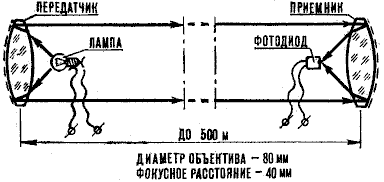
For the construction of optical communication lines is not requires special permissions, it can be successfully used in difficult terrain, sport, tourism the campaigns. The line operates on the principle of optical phone, range communication up to 500 m (Fig. 1).

Media in it are not the radio waves and light. To make the beam to "fill" the necessary messages it must be modulated. This is done so. The electric signal from the microphone is fed to the low-frequency amplifier, where instead the loudspeaker is switched on a light bulb from a flashlight. Current flowing through a light bulb that changes depending on the transmitted signal, then changes the brightness of the bulb. Luminous flux is modulated by the audio frequency voltage. Beam directed the side of the receiver, needs to be well focused to less scattered.
In the receiver the signal demodulated, that is decrypted. Beam through the lens falls on the photosensitive element, which is converted into electric oscillations of audible frequency, which then amplified and played back through headphones.
For one-way conversation within line likely enough to have one sleeperettes and one svetopriemnik. For bilateral relations will need two identical sets transceivers.
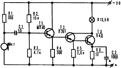
The optical transmitter of the phone (Fig. 2) operates from a carbon microphone MK1. Voltage frequency audio microphone through the coupling capacitor C1 falls to the input of a three-stage the amplifier.

The transistors of the amplifier is connected to the circuit composite transistor. Such a low-frequency amplifier gives a significant the gain of the signal current, which is extremely important to power light bulbs filament L1, which is the radiating element of the transmission device. The voltage supplied to the lamp when the input signal has to be 4-4,5 In, its value is set by resistors R2 and R6.
Details of the transmitter, except for the microphone and light bulbs, are mounted on the Board of foil Micarta or PCB. Can use and also the finished circuit Board with a rigidly reinforced her petals or pillars of brass. The microphone MK1 is connected to the amplifier shielded wire.
The transistor T1 type MP or MP41-MP42. It the static gain of current may be in the range of 50-60. The transistor T2 type P-P with any letter index and coefficient gain at least 50. Finally, as the transistor TK can to use any
power semiconductor device, for example from series P-P. It is important that the gain was not less 20.
The transmitter operates coal type microphone The MC-10 or MC-59.
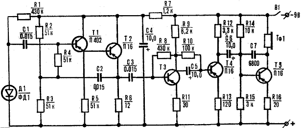
The receiver circuit (Fig. 4) is very simple. She is pjatijazicnij low-frequency amplifier for low-power the transistors T1-T5, the input of which includes a photodiode D1, and the output - phone TF1. Adjusting the volume of the received signal is not provided just because the signal level does not exceed the allowable for this amp values. However, if you need to install this regulator, it is possible to replace the constant resistor R12 in the collector circuit of transistor T4 is possible for AC to the middle pin of which first connect the capacitor C6.

Details of the receiver, as well as details the transmitter mounted on the circuit Board of insulating material. Sizes fees are determined by the dimensions of the parts.
The photodiode D1 is connected to the flexible amplifier shielded wire.
The transistor T 1 low-power, high-frequency type P-P, and the transistors T2-T5 type PH or MP39-MP42 with any letter index. The gain of the transistor current can be within 50-60. Phone TF1 - electromagnetic, type K-47, or any other, having coil resistance 60-130 Ohms.
Photodiode D1 type FD-1. You can replace homemade, made of two low-power transistors MP39-MP42.
Mechanical alteration of one of the transistors is reduced to a neat delete (remove) the upper part of the body of the device. The resulting transistor is connected with the second (serial) the transistor as follows. The collectors of transistors through a resistor the 4.7 Ohm resistance is connected to the negative terminal of the source power, and then connect to a resistor R1 and a capacitor 1. Base phototransistor through a resistor 75 Ohm associated with positive terminal of the power source is connected and also the emitter of the additional transistor. Finally, the emitter of the phototransistor connect with the base of the second transistor.
Power supplies receiving and transmitting devices are sets consisting of two connected in series battery type 3336L.
Now for light-emitting and light-receiving devices. So as shown in Fig.1 the scheme worked well, need to install along with the lenses spherical mirror.
But there is more simple installation option. For it need two flat-wyluli converging lens with a diameter of 30 - 40 mm with a focal length of 70-80 mm. The light emitter and sitoriabini have exactly the same design, which is a cylindrical body of the tube out of cardboard the lens on the outside. In the depth of the housing of the transmission device, the focus of the lens is the light bulb, and in the case of receiver - a photodiode or other photosensitive element. The back side of the emitter housing is spherical disk of cardboard, covered aluminum foil. In svetopriemnik the bottom of the tube covered with dark paint.
Configuring the optical system is finding the right position (at the point of focus of the lens) lamp or photodiode.
Each unit of the optical communication lines should to be provided with a viewfinder (you can use a simple framework the viewfinder from the camera).
The viewfinder is needed to combine optical systems transmitting and receiving devices.
Before the establishment of the transmitter you want to disable the microphone to the amplifier and the resistors R2 and R6 to set the optimum brightness the illumination of the light bulb L1. Then to the input of the amplifier to connect the radio, electrophone or tape recorder. If you gradually increase the volume, and the brightness of the bulb will be changed. After this test again connect the microphone to the transmitter, say in a few words, thus making sure that the brightness of the beam also changes.
Check operation of the receiving device. At first light the photodiode by the light from the bulb, included in the network AC. In the earphone, you should hear a distinctive noise. If cross arm beam of light, then there came a light tapping - so, photodiode or improvised by the phototransistor works fine. Then the photosensitive device is set so that the signal was maximum.

After checking the operation of the device at close distance (5-8 m) need to test it in "field" conditions. Success in communication largely depends on proper adjustment of optical systems.
Publication: www.cxem.net


