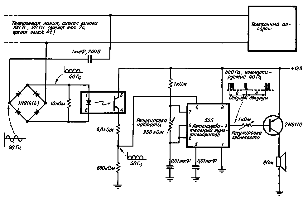
Optocoupler for transmitting a call signal to a separate call to the device to prevent overloading of the telephone line, to avoid confusion with the telephone company and to maintain the performance of the line receiving a signal. By means of optocouplers can also include other devices such as the apparatus for recording telephone messages. Calling device consumes a current of 10 mA at a ringing signal and almost no load on the line for speech signals DC.
In this scheme, the PCP transmits the call signal to the rest of the calling device, isolating it from the telephone line. The output current of the optocoupler controls the type 555 timer, which is enabled by the self-oscillating circuit of the multivibrator. The audio frequency of the multivibrator is amplified and fed to a remote loudspeaker, which produces an audible signal when a telephone network tone.

(click to enlarge)
As shown in the figure, the call signal with an amplitude of 100 V and a frequency of 20 Hz has a turn-on time of 2 s and an off time of 4 s. This signal is supplied to a light emitting diode of the optocoupler through capacitor 1 ICF with the reactance of 10 ohms at a frequency of 20 Hz, which limits the current LED value of 10 mA. The switching frequency of 40 Hz in the loudspeaker of more pleasant to the ear than 20 Hz, so call signal frequency is doubled by a full-wave bridge rectifier.
The output signal of the optocoupler frequency of 40 Hz is supplied to the reset input of the multivibrator collected on the integral type 555 timer. The natural frequency of the multivibrator is set equal to 440 Hz. This frequency, corresponding to the tone in the handset, the most convenient for the subscriber. The frequency of the multivibrator is adjustable 250-kω potentiometer. The fill factor of the multivibrator is set with a 1-kω resistor and is theoretically equal to 50%, but in practice it is 35% due to the modulation of the switching signal.
The output signal of the timer can without amplification to apply for a small speaker through the serial current-limiting capacitor. However, in some cases, such power may be insufficient. To enhance the rectangular output of the 555 timer is necessary to use a switching amplifiers. To obtain maximum efficiency and power output at currents less than 50 mA, the integral timer must be used as a source, but as a consumer power, so switching amplifier is going on pnp-transistors.
When the parameters of the components shown in the diagram, its power output of the system is 5.5 W, which is close to the theoretical limit for a single speaker with an impedance of 8 Ohms, Vcc 12 V and the fill factor of 35%. Using an amplifier with high gain or a speaker with a lower impedance, it is possible to obtain a higher output power. In this case, you can use multiple speakers in parallel-sequentially, with separate volume control through the l-shaped resistive circuit.
In the quiescent mode circuit consumes from the power source 12 To 120 mW. This power can be reduced to zero, using dual OPTRON. Second insulated and synchronous output is used to control static switch on the triac, which includes a power source.
Although the circuit with optocoupler almost no load on the line, it is still necessary to notify the telephone company about installing the calling device.
Author: Krangel ml.; Publication: N. Bolshakov, rf.atnn.ru


