Increased interest in the manufacture of cordless telephones is constrained by the complexity of the circuit and a technical solution, due to the principle of operation. For example, the radiotelephone "RTF-92, published in [1], is complicated in manufacture and adjustment, requires the manufacture of a large number of coils and transformers
In drafting the proposed radiotelephone task was to create a wireless phone, are available for the manufacture of novice radio Amateurs. The method of tone control doesn't allow this, so the basis for the operation of the radiotelephone on the method interrupts the carrier. This allowed to simplify the scheme and provide the following advantages:
- work in full duplex (simultaneous talk and listen);
- high signal quality (wideband FM modulation);
- powered stationary unit completely from the telephone line;
- high efficiency handsets (for :Chet simplicity of the scheme);
- the simplicity of the components and the ability to increase transmitter power.
Consider the operation of the radiotelephone.
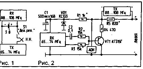
The radiotelephone handset (Fig.1) is in the door of the reception, the transmitter her off. In a stationary telephone set (Fig.2) works well as one only the receiver. Phone with caller ID is auto-pick up. When you receive a call from a caller is automatically included stationary transmitter device and transmits the call to the cordless handset. The call transmitter is enabled handsets and the system is ready to work in full duplex mode.
If you call from the cordless handset is powered transmitter toggle switch S1"Dej.dir.". The carrier signal is received by the receiver stationary unit, with it, the led turns on fine tuning. In standby mode, the transistor VT1 (Fig.2) is closed. The voltage from the led, the transistor opens, the resistor R5 occurs a voltage drop, which feeds the transmitter is stationary part. When dialing on the radiotelephone handset interrupt occurs the power (and the carrier) on the number of times corresponding to the figure. Accordingly the same time the led goes out, the voltage which switches the transistor VT1. Thus there is a dial in line. In the transmission of information low-frequency signal output from the VLF receiver is supplied to the base of VT1 for modulation. In the absence of a phone with caller ID, which includes the mode of auto-pick up, you can install the electronic relay performing the auto-pick.
Choice of transmitters and receivers for radio. The choice of the receiver depends on the capabilities and qualifications of radio Amateurs. The main criterion for receiver enable, controls and the transistor VT1 can be placed in the receiver. Can also be installed in the housing of the receiver socket, and output the control voltage, and the control scheme to collect in a separate housing. In this embodiment, the receiver can be disconnected and used for its intended purpose.
If you will use the import receiver (they usually have one special chip), and in the absence of circuit diagram of the receiver point where voltage fine adjustment, can be found experimentally by the tester to increase the DC voltage when receiving the signal of the carrier frequency of the transmitter handsets.
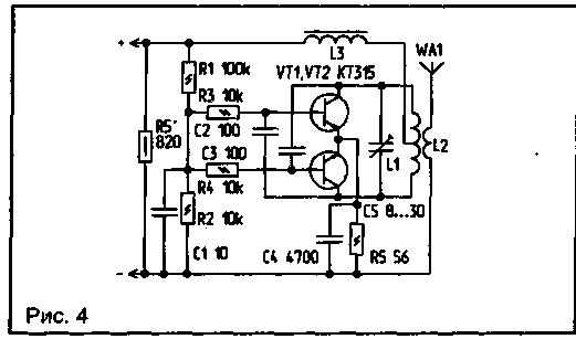
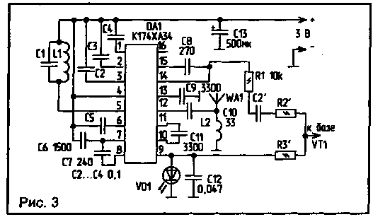
To simplify the design of the stationary transmitter apparatus (Fig.4) is powered by the telephone line. Its power is limited by the capacity of the telephone network and depends on the voltage drop across the resistor R5. The value of R5 is chosen so that when raised the handset on it fell 15...18 In (transistors should be slightly warm). The range of receiver handsets - quiescent current, since it determines the time of continuous operation. Economical receiver with low-voltage power supply can be assembled on the chip CHA in the circuit shown in Fig.3. In its absence, you can use ready-made miniature receiver with access to the phone. Board sizes are such that allow you to freely install it in the handset of the cordless telephone. The same receiver, but the range 65...74 MHz, can be used for stationary apparatus. The receiver consumes a small current, so it can be powered from the telephone line. But as the size of the receiver for the stationary apparatus is not critical, for this purpose you can use a portable receiver with built-in power supply unit type "Ocean".
The procedure of finalizing the stationary receiver apparatus. To control the transistor VT1 (Fig.2) from the receiver uses two signals: voltage fine tuning to dial in line, and the voltage of low frequency for modulation. If the size of the phone is largely determined transmission power of handsets, and she, in turn, depends on the supply voltage. If you do not want long range, for the transmitter you can use the power of the receiver (Fig. 1). The choice of source voltage and its magnitude is determined by the size handsets
A schematic diagram of a radiotelephone transmitter tube is shown in Fig.5. The master oscillator of the transmitter is performed on the transistor VT2 type CP. The frequency of oscillation is determined by the elements L1, C3, C5, VD2. Frequency modulation can be realized by applying the modulating audio frequency voltage to the varicap type VD2 SW109. The operating point is set by the voltage supplied through the resistor R2 of the voltage regulator. The stabilizer includes a constant current generator FET VT1, the Zener diode VD1 and the capacitor C2. The power amplifier is performed on the transistor VT3. The mode of operation of the amplifier is set by the resistor R4.
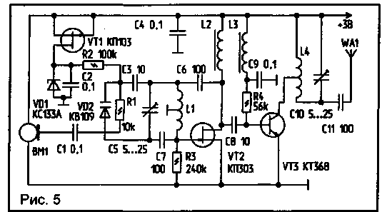
Inductors L2 and L3 can be anything with an inductance of 10...150 mH. Coils L1 and L4 are wound on a polystyrene frame with a diameter of 5 mm with a setup cores 100 HF HF or 50. The number of turns is 3.5 with a branch of the middle, the winding pitch 1 mm, wire - sew of 0.5. Setup is to install the necessary frequency oscillator capacitor C5, to obtain maximum power by adjusting the resistance of the resistor R4 and the frequency control circuit capacitor 10.
In the stationary transmitter apparatus (Fig.4) resistor R5 is inserted in the opening of one of the wires of the telephone network. When hook telephone set or activate the auto-pick in the circuit current appears, which depending on the type of device and the state line is in the range of 10...35 mA. This current flows through resistor R5 causes the voltage drop of the order of 15... 18 In that nourishes the transmitter. The oscillator of the transmitter is assembled in a conventional push-pull circuit, transistors VT1 and VT2. Frequency modulation is due to the change of the line voltage and, consequently, changes the voltage at the bases of the transistors. The frequency is settable circuit L1, C5. Coil L1 is wound on a polystyrene frame with a diameter of 5 mm and contains 4 round of PEV 0.5 mm with a branch of the middle. Coil L2 is wound on top of L1 and has 2 turns of the same wire. The setting is done by a busy telephone line by means of the control circuit L1, C5.
The phone provides the communication range within 300 meters, but if you install an additional power amplifier radio tube and the stationary part can easily increase the range of 10 to 15 km. When installing the radio in the car washing handsets is better done by an onboard battery.
Consultations and also collected schemes transmitters can be obtained from the author.
Literature
Author: N. Martynyuk, Brest region, Kobrin
In my article received a lot of letters, therefore, attempt to answer basic questions on the pages of the magazine.
Relay auto-pick (Fig.1) made on the chip CLA scheme of a single vibrator.
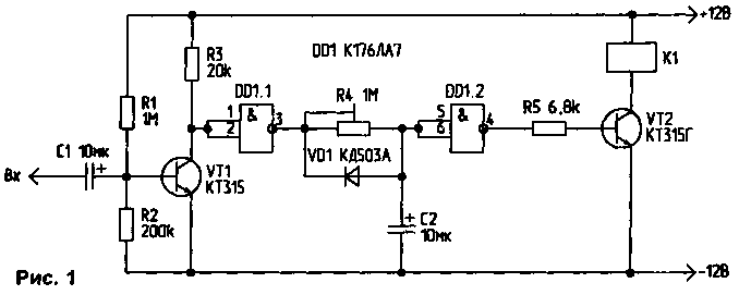
Because the receiver and transmitter stationary part are powered from the telephone line, increasing the range of operation is only possible by increasing the sensitivity of the receivers, since the power of the stationary transmitter is limited by the capacity of the telephone line, and a portable transmitter - capacity batteries. Manufacturing in the home high-power transmitters and sensitive receivers requires a certain amount of experience, instruments for adjustment and scarce radio component, therefore it is better to go the other way, if you want a phone with a range of up to 20...30 km.
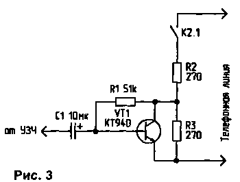
Currently relatively inexpensive you can buy a good 40-channel radio. By simple modifications of the power may be increased to 8...10 W, and based on such radio stations get a good phone with great range. A functional diagram is shown in Fig.2, and the schematic diagrams of the electronic relay nodes delay of auto-pick out and discussed in Fig.3, 4.
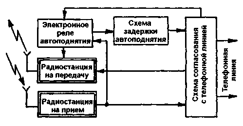
Fig.2

(click to enlarge)
In the standby mode is enabled only radio station, working on reception. When receiving a call signal from the telephone line, the ringing voltage is applied to the electronic relay of auto-pick, which is triggered and the Executive relay includes a radio station, working on the transmission. Ringtones are served on her microphone input and transmitted over the air to the mobile station. After 5...6 triggers the delay circuit of auto-pick, and there is a connection with the calling subscriber.
Since the reception is on the same channel, and transmission to other mobile stations in the transmission to switch the channel. For example, the reception is on the 9th channel, and before pressing the PTT on the transfer, you must include the 19-th channel.
Author: N. Martynyuk, Brest region, Kobrin; Publication: N. Bolshakov, rf.atnn.ru


