It often happens that one telephone line connected telephones, the ringing signal is sent simultaneously to all devices. Therefore, it is impossible to determine which subscriber is called. The proposed the device allows you to transfer a call on a parallel phone is easy by pressing the button.
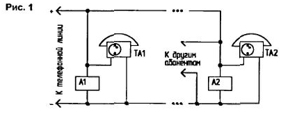
The scheme of connection of telephone sets TA1, TA2, and devices call (subscriber unit) A1, A2 to a telephone line is shown in Fig.1.

To phone line you can connect multiple devices and the subscriber unit. The basis of the device taken the scheme from [1]. which greatly simplified.
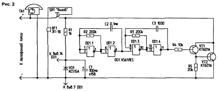
Diagram of the device of the calling extension telephone shown in Fig.2.

In standby mode, the device consumes little current from the telephone line, as line is connected to the piezoelectric emitter BF1 has an infinitely large DC resistance. The voltage of the telephone line is usually 60 V. It has a certain polarity, which should be considered in connecting a subscriber's set to the line.
When you receive a call signal to the subscriber picks up the handset, telephone line current begins to flow, and the line voltage drops to 10...20 In (depends on the parameters of the telephone and its distance from the telephone station). To transfer a call to another subscriber must press the button SB1 "Challenge". In this case, through the no button contacts voltage is applied to parametric voltage regulator R1-VD1, and with him - on the call generator on DD1 chip and the transistors VT1, VT2. The first generator for logical the elements DD1.1, DD1.2 generates pulses with a frequency of about 20 Hz, and the second the generator on the elements of DD1.3, DD1.4 - pulses with a frequency of about 2 kHz. The base transistor VT1 is fed dual-frequency modulated signal.
Transistors VT1 and VT2 periodically close the telephone line. forming such the call voltage pulses, and the other party (or more) an audible signal at the emitters BF1, which is provided with a telephone the vehicles. On the appointed amount of received signals or by their nature other subscribers will understand who should pick up the phone. The selection of resistors R2. R3, you can change the frequency of the ringing the signal that will enable the identification of subscribers from each other. When talking on telephone from the emitters may be heard weak slurred speech that is the busy signal telephone line. At the time of call connection parallel the subscriber caller hears in his pipe signal call forwarding.
Details. Transistors CTE can be replaced by CTA, CTA. CTA and others, designed for allowable voltage emitter-collector of at least 80 C. SB1-type BM1-1. The piezo oscillator SN-1 can be exchanged for ZP-2. ZL-3. RFP-18, RFP-19.
The device is assembled in a plastic case made in the form of coasters telephone apparatus. Most of the elements of the device is placed on a printed Board. The call button is located on the side of the housing, there is the system.
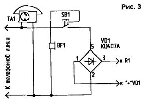
Connecting this device to the telephone line must be produced polarity, which is a disadvantage of this scheme. In Fig.3 shows how to include a bridge rectifier in the subscription set, to connect the device to the telephone line in an arbitrary polarity.

In as a bridge diode assemblies VD1 you can use the build KTS405. CC, CC with any letters, as well as imported RS201. RS202. DB101. DB102. BR305, BR31.
This device can be used to invoke parallel subscribers and the absence of an incoming call from telephone station. It should only to agree on the number of ringing signals from different subscribers.
Literature
Author: A. Evseev, Tula.


