This device is intended to prohibit long-distance communication with a telephone device which is connected through it to the line. The device is assembled on the IC series C and is powered by the telephone line. Current consumption - 100...150 μa. When it is connected to the line to observe polarity. The device operates with a PBX with the voltage on line 48 60V. Some of the complexity of the scheme is due to the fact that the algorithm of the device implemented in hardware, unlike similar devices [1], where the algorithm is programmed using a single chip computer or microprocessor, which is not always available to the radio Amateur.

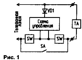
Functional diagram of the device shown in Fig.1. In the initial state of the keys SW open. THE one connected through them to the line and can take a tone and dials the number. If after removal of the tube first dialled number will be the index of access to long distance communication, the control circuit actuates the waiting multivibrator, which closes the keys and terminates the loop, thus producing the rebound PBX. The index of the HSE can be anything. This scheme you can set the number "8". The off time of the device from the line can be set from fractions of seconds to 1.5 minutes.

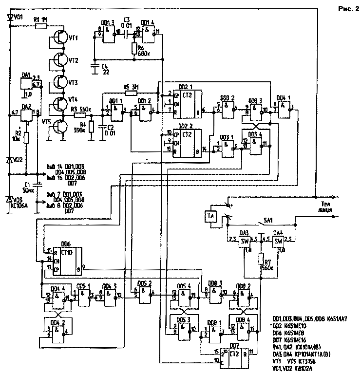
Schematic diagram of the device shown in Fig.2.
The elements DA1, DA2, VD3 VD1..., R2, C1 harvested the source IC supply voltage of 3.2 V. the Diodes VD1 and VD2 protect the device against wrong connection to the line. Transistors VT1...VT5, the resistors R1, R3, R4 and the capacitor C2 is assembled, the voltage level Converter of the telephone line to the level required for MOS circuits. The transistors in this case is included as a Micropower Zener voltage stabilization 7...8 V At a current of several microamperes [2]. On the elements of DD1.1, DD1.2, R5, R3 assembled Schmitt trigger, providing the desired steepness of the pulse edge set. Elements DD1.3, DD1.4, C3, C4, R6 form a clock pulse generator with a frequency of about 80 Hz. On chips DD2, DD3 assembled gauge the position of the tube, and DD4.1 - the selector pulse dialing.
The counting of the pulses is set by the counter DD6. IC DD4.2...DD4.4, DD5 form a scheme that allows the counting of pulses in the first set of digits and prohibiting the counting of pulses when the subsequent set of numbers. On the IC DD7, DD8 assembled waiting multivibrator, managing keys DA3 and DA4. The switch SA1 is used to turn off the device. The capacitor C4 is needed to improve the initial startup of the generator.
Literature
Author: C. Kopylov, Tiraspol; Publication: N. Bolshakov, rf.atnn.ru


