


")

The exact orientation of foster TV antennas at a considerable distance from the transmitting station often causes difficulties. And very often used in such cases, the method of installing them on the image on the TV screen does not lead to the desired results. And the accuracy of the location of the antenna greatly affects the image quality, especially color.
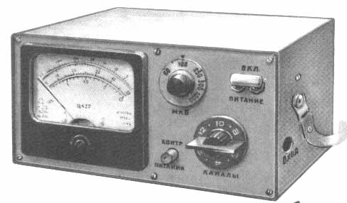
Will greatly facilitate the orientation of the antenna device. It can be used when installing antennas for individual and collective use in any of the 12 channels of the range metre waves in the city and in the countryside. This device allows to measure the signal level at the antenna output and to determine the possibility of obtaining good quality images, i.e., a coverage area, to assess the serviceability of feeder systems and antenna amplifiers. In the fringe area of reception with its help it is possible to identify the point of installation of the antenna on the ground.
The device provides measurement of the voltage of the radio frequency (RF) in the range of 60 mV to 1 mV (with removable divider 1:10 to 10 mV). The relative measurement error is not more than 30%. Dimensions - HH mm, weight - not more than 1,5 kg. the device is Powered from four batteries 3336L, current consumption is 40 mA.
Block diagram of the device depicted in figure. Measured the voltage, is input to the channel selector, where it is amplified and is converted into an oscillation of the inverter. From the output of the if amplifier the signal is fed to the rectifier, and allocated the DC component at the input of the DC amplifier (UPT), loaded output voltage indicator.
The measuring principle input voltage Uвх based on the determination of the angle of rotation of the engine, variable resistor R6 in the circuit of the negative feedback (EP) covering the SIC. The value of the angle is directly proportional to the signal level of the Uвх, if this resistor is set on the device RA1 is the same output voltage Uвых.
(click to enlarge)
Schematic diagram of the device represented in Fig.1. It is assembled on the basis of the channel selector SC-M-20 [I]. A three-stage if amplifier (circled dash-dotted line) is formed on the printed circuit Board from the same selector (the details of the amplifier is designated in accordance with his concept, and new elements and compounds in bold). To obtain the same gain of the device on all channels serves as a divider R10-R22 and the switch SA1 is fixed to the axis of the channel selector and providing a bias voltage in the circuit of automatic gain control (AGC) of the selector and in the circuit of the bases of the transistors of the first and third stages of the if amplifier depending on the channel.
The UPT assembled on OU DA1 covered by the EP through resistors R4, R6. Balance OU trimming resistor R3. To the output of the SIC through a resistor R8 and click SBI microammeter connected RA1. At the risk of the reference arrow of the microammeter is established by calibrating the device, a trimming resistor R8. Resistor R9 achieve deflection of the microammeter to mark 12 V mode control voltage (button SB1 is pressed).
The SIC is powered by the stabilized voltage ±6 V from dual supplies (Fig. 2), and the TV tuner and the if amplifier is from him, but 12 V (pin -6 In connected with them common wire). Based on a device described in [2]. The stability of the supply voltage is maintained at a voltage reduction of the battery GB1 and GB2 to 6.7 V. Current. consumed by the stabilizer, does not exceed 1 mA. The device is operable and when you decrease the voltage of each battery to 5 V, but in this case deteriorates the sensitivity and interferes with the graduations of the scale, therefore, the device can only be used as an indicator when the orientation of the antennas.
Fig.2
At high input levels can lead to saturation of the transistors in the cascades the TV tuner and if amplifier. In such a case, between the input of the device and plug the antenna includes a removable divider 1:10. To ensure the safety of the housing is connected to the screen input coaxial socket XS1 through the coupling capacitor C1, and the socket mounted on the insulating strip.
The device incorporates resistors SP-1-A-0.5 (R6). GPA-16 (R3, R8, R9, R23, R24) and VS (the rest). Button SB1 - P2K-latched in the depressed position. Microammeter - anyone with a current total deviation of 50… 100 μa, for example, from avometra C.
Coils L7 and L8 are wound on a polystyrene frame (from the selector SC-In-1) with a diameter of 5 and a length of 17 mm with brass podstroechnik and contain 20 turns of PEV-1 to 0.2. The distance between the coils is 2 mm, the winding turn to turn.
The details of the device mounted on a vertical duralumin chassis dimensions HH mm, serving front panel. The housing unit is made of plastic aluminum alloy with a thickness of 1 mm. the housing of the channel selector, the front panel and the casing of the device are electrically interconnected.
The switch SA1 fixed on the tail of the axis of the channel selector. His rolling Board serves as the drive switch channel selector SC-M-20, which removed the coil, and between the contacts soldered the resistors R 11 - R22 divider that provides a voltage gain correction the TV tuner and if amplifier. The ledge in the Central hole of the disc is removed by a needle file, and the hole reamed to a diameter of 5 mm (see Fig.3 a,the metal contacts on the shaded disk shareware) .
Fig.3
When drilling holes with a diameter of 1.2 mm in the sleeve of the disc insert metal sleeve (Fig. 3, b). Then with the tail axis selector channel selector remove the locking spring and brass strip, put on an axis drive switch and drill hole with a diameter of 1.2 mm dowel. After fixing the drive pin retaining spring set in place.
Stationary contact 3 of the switch (see Fig. 4) made of a current collector plates of the channel selector SC-M-20 and secured between the parts 1 and 2 insulating strips, which in one of them (2) needle files propylene grooves with a depth of 0.6 mm. strap Part is made from hard rubber or Micarta (part 1 thickness of 1.6 and part 2 of a thickness of 3 mm) in the drawing, is shown in Fig. 3, g in the text, and after installing the contacts stick together, and then fastened with 4 rivets with a diameter of 1.5 mm with countersunk head. The bar is placed on the mounting position of the high-pass filter selector (see Fig. 3), and the filter is mounted on elongated insulating supports (Fig. 3, in).
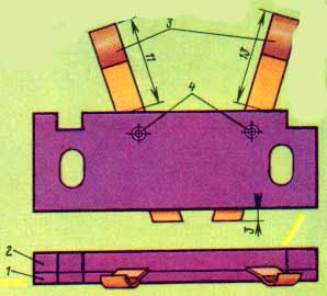
Fig.4
The printed circuit Board of the if amplifier shown in Fig. 5. New connections and details shown by a dotted line (shaded portions of the foil are removed from the Board). When mounting the printed circuit Board selector SC-M-20 first delete all current contacts. Then translate the RF amplifier transistor V1 (see Fig. 1) in the mode of if amplifier on the circuit ABOUT why the throttle in its emitter circuit replace the bridge, and the capacitors C4, C5 are removed. The if output of the channel selector is connected to the condenser Sat. From the collector circuit rule out the capacitors C9, C10, the output resistor R4 is connected to the junction point of the coil L5 and the capacitors C13, C14 in the base circuit of the transistor V2, the resistor R5 may be given. The collector of transistor VI is connected to the junction point of the coil L5 and capacitor C12, and the jumper connecting the collector with the collector contact contour coils are removed. If output transistor V2 through a capacitor C is connected to the base of transistor V3.
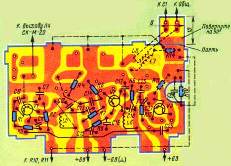
Fig.5
Heterodyne transistor V3 is also transferred to the mode of the if amplifier, but according to the scheme MA. To this end remove the capacitors C19-C24, coil L7 and the resistors R10, R12, a resistor R13 is reduced to 680 Ohms, and the capacitance of the capacitor C25 is increased to 4700 pF; in the transistor base circuit includes a divider of the resistors R10, R11 and capacitor C20, the midpoint of which summarize the AGC voltage from the switch SA1. In the collector circuit of transistor V3 include coils L7, L8 and resistor R14.
The printed circuit Board of the if amplifier added a small plate of foil fiberglass with a thickness of 1 mm, soldered perpendicular to the main. It serves to connect the coil L8 with the SIC.
The establishment of the unit starting from the voltage stabilizer. The engines of trimming resistors R23, R24 installed in the middle position, disconnect the regulator from the circuit and load each source by a resistor 510 Ohm resistor with a power dissipation of 0.5 watts. After connecting the battery, measure the voltage at the output of the regulator and the resistors R23, R24 set them equal to +6 and -6 V (±5%). If this fails, choose the Zener diodes VD3, VD4.
Then proceed to the adjustment of the SIC and the if amplifier. The engine of the resistor R3 is set to the middle position, the resistor R6, the SIC - in the position of the minimum, and resistors R8 and R9 and a ceiling of resistance. The coil L8 is disconnected from the capacitor C2 DCA. The channel selector switch on the 12th channel (usually it is the lowest sensitivity), and to the movable contacts of the drive switch SA1 fluster variable resistor of 2,7 kOhm (instead of the resistor R11), setting its engine in the middle position. Then connect the power source and pressing the button SB1 "Counter, Pete." trimpot resistor R9 sets the arrow of the microammeter at any point of the scale, which will further be used to control the voltage of 12 V. Further trimming resistor R3 achieve zero readings when you released the button. This operation is repeated by setting the slider of the variable resistor R6 in the beginning to middle and then to the bottom (by the scheme) position. After that, the rotation of the engine variable resistor connected to the switch SA1, set the initial offset voltage of +8 V, applied to the AGC input of the TV tuner and the if amplifier.
Next, solder the coil L8 to the capacitor C2, again set the slider of the variable resistor R6 in the position of the minimum of resistance and the graduate scale on the axis of the limb of the resistor. With a signal generator to the input device serves unmodulated voltage 200…500 mV frequency equal to the mean frequency of the custom TV channel. Gradually increasing the resistance of the variable resistor R6, set the arrow of the microammeter to the middle point of the scale. If this fails, reduce the resistance of the tuning resistor R8. The maximum deflection seek first the knob lo channel selector, and then alternate rotation of trimmers coils L5 - L8. Finally, a variable resistor connected to the switch SA1, achieve maximum sensitivity of the device according to the largest deflection, and then by measuring the resistance of the entered part of the resistor, replace it with a constant.
Then reduce the RF voltage at the input of the device to 60 mV and translate the handle of the resistor R6 to a position close to the maximum resistance (little short stop), which corresponds to the maximum sensitivity of the SIC. A trimming resistor R8 set the arrow of the microammeter to the middle point of the scale and mark it mark "Countdown", and the limb of the variable resistor R6 is applied in opposite risk of stating the RF voltage of 60 mV. Similarly, when the input of the device voltage RF 100, 200, 500, 1000 mV and each time setting variable resistor R6 arrow microammeter at risk of "Countdown", is applied to the limb of the resistor the other mark. Thus it is necessary to ensure that when you increase the voltage of the RF PA RF input of the device tract but was overloaded.
Next, translate the selector on the 11-th channel, and the limb of the variable resistor R6 to 100 µv". To the contacts of the switch SA1 in series with the resistor R11 (in place of the resistor R12) include a variable resistor of 47 Ω and by rebuilding the generator to the center frequency of this channel, is fed to the input of the device, the RF voltage of 100 µv. Rotating engine variable resistor, set the arrow of the microammeter at risk of "Countdown", then it is replaced with a constant (R12) of the same resistance. Just choose the resistors R13-R22 on other channels.
When the orientation of television antennas, the device is used as an indicator: turn the antenna to achieve the maximum deflection of the microammeter.
For assessing health feeder systems and antenna amplifiers measure the voltage of the received television signal in their output and compare it with the signal level properly working devices.
In the case of measuring a color image in the area of reliable reception at the input of the TV set variable divisor of n, reducing them to the RF voltage, pursuing his values, wherein the common synchronization and the color is still quite stable. Then measure the device voltage, RF output divider. Its value can approximately be guided to assess the zone of reliable reception.
When choosing the place of installation of the antenna in the fringe area of reception measured voltage of the RF signal at various points in terrain. The antenna set in place maximum the signal level.
Literature
Authors: I. Gladkov, V. Efanov, Fazylov, Odessa; Publication: N. Bolshakov, rf.atnn.ru