


")

Repair video cameras (camcorders) is one of the most difficult household the video equipment. It is associated with a high degree of control of their nodes and its the lock malfunctions. The repair of such vehicles in published article by the example of SAMSUNG camcorder VP-U2.
Camcorder very complex consumer electronics products. Their qualified repair only by experienced professionals with service documentation modern measuring equipment, tooling and spare parts. From the number of firms, providing warranty repair sold in Russia and CIS camcorders, the most famous SONY MATSUSHITA (PANASONIC), SAMSUNG. They are all equipped requires a relatively large number of its authorized service centers. Much less in this regard made by HITACHI, SHARP, JVC and others. Camcorders such as CANON, FISHER, ORION, UNIVER-SUM and outside. Moscow can take to repair only regular workshops or individual experts.
Warranty service is basically identical in all firms that sell video cameras in Russia. Let's take a look at the example of South Korean company SAMSUNG, implements for sale affordable camcorders VIDEO format-8 (SAMSUNG: VP-U10 for $ 415., VP-N for $ 420. is for the summer 1997). Conditions service contain five items: 1 - the warranty period is 12 months (SONY gives a two-year term); 2 - warranty covers only the cost of spare parts and the cost of the work, i.e. transportation of the equipment is ensured by client, which in our conditions is an onerous (about 30 of commissioners service centers of SAMSUNG are in several regional centers); 3 - repair should occur only in authorized service centers; 4 - warranty does not apply to the video heads, punched and deformed body, etc.; 5 - the warranty does not cover damage from accidents, improper use, fire, flood, and on the apparatuses, renovated in others workshops.
In addition, the warranty is valid only when filling out the warranty card (name, address, customer phone, address, signature and stamp of the dealer). Consequently, a huge amount of equipment sold at markets, stalls, imported privately from abroad, etc., were out of warranty service. More headache owners of cameras delivers faulty equipment after the warranty period or manufactured by companies not with service offices in Russia. Given this, it is justified publication of materials for advanced Amateurs and professionals repair cameras.
According to the observations of the author of a significant number of faults modern camcorders accounts on the system that provides power to all components and engines. For cameras typical of the versatility of such systems, so the use the terms "power source", "electric drive", "stabilizer", etc. not quite correctly.
One of the most important requirements for cameras should be called the provision of small compatible from independent sources of supply. For most vehicles formats VHS-C and VIDEO 8 power consumption is in the range 5…10 watts. Especially low power consume camcorder from SONY with the function of STAMINA, for example, SONY - CCD-TR820E she's only 3.5 watts [1]. So impressive characteristics obtained by minimizing compatible electronic part cameras and significantly increase the efficiency of power systems, circuitry which with much more complexity than other types of household equipment.
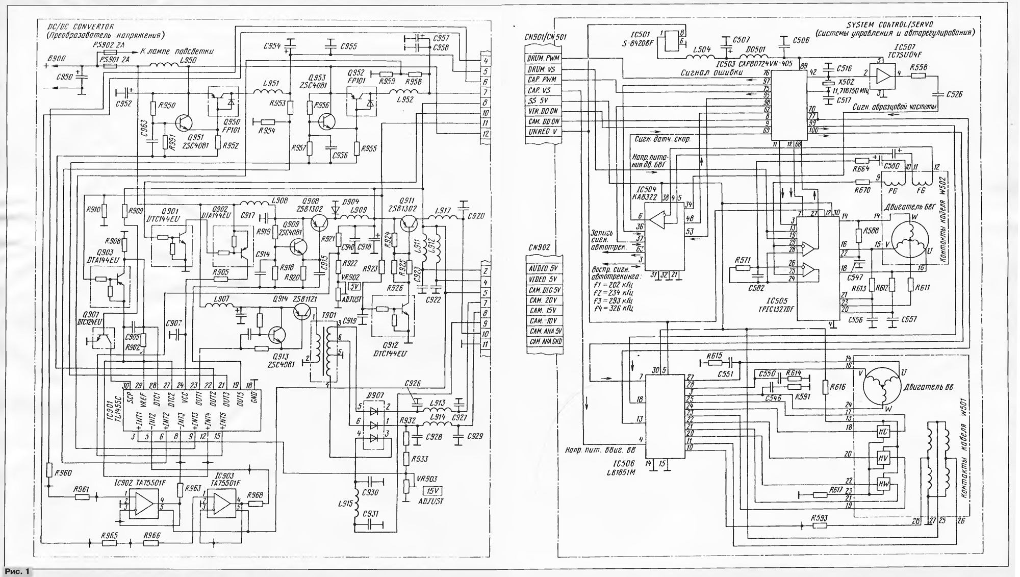
In Fig. 1 shows a simplified schematic diagram of a system power the camcorder SAMSUNG VP-U12. It is based on the pulse voltage Converter (DC/DC CONVERTOR), the DC voltage 6 which is supplied with the battery (NP - 7HPN, etc.) or network adapter AA - ER representing switching power supply, combined with the charger. Primary the voltage across the battery terminal V and pin 12 of connector CN901 comes on management system and self-regulation. It without any switching it passes through a voltage regulator on the chip IC501 (output - +5 V) on contact 89 (VDD) microprocessor control IC503 type SHR SONY.
(click to enlarge)
The continued operation of the voltage Converter depends entirely on commands of the microprocessor, with many output voltages covered by the system control and when you reject one of them from normal inverter operation is blocked. This algorithm is typical for most modern cameras. This sometimes causes difficulties in diagnosis, as something to check for a few seconds the active state after switching on highly problematic. Subject to certain conditions manual switch-on possible most drives. But if it is not possible disconnection of the inverter, the necessary continuity of all its output circuits and power components.
In the absence of a short circuit on common wire and punched elements, it is possible use a manual startup mode. In the present case do the closure of the contacts 10, 11 and 12 of the connector CN901. This opens the key on the transistor Q902 and a voltage of +6 is supplied to the output 24 of the multifunction chip IC901. All stabilizers Converter made by key schemes and involve the feedback so that the output voltages are stabilized by changing the duty cycle of the pulses arriving at the keys with chips IC901. Due to the this ensures high efficiency of the transducer, eliminating the need removing heat from it, and the use of high-performance semiconductor devices and elements for the mounting surface and allowed to post it on the circuit the Board is very small in size.
Most devices of the camcorder is supplied with the voltage +5 V with key stabilizer transistors Q908, Q909 (start with output 19 - OUT5 chips IC901) with protection device against short circuits (emergency mode corresponds to the large resistance of the key transistor Q907).
Set by the resistor VR902 voltage +5 V is supplied to the control system and self-regulation (chain SS5V), through the inductor L911 - channel sound via the throttle L912 - channel image, and through the switch transistor Q911 - on camera camcorder. Necessary to power the nodes of the chamber parts voltage +15 V (CAM.15V), +20 (CAM.20V), -10 (CAM.-10V) forms pulse cascade transistors Q913, Q914, transformer T and diode the Assembly D907. Voltage +15 In trimmer set VR903.
Besides the stabilizers in the composition of the Converter includes parts the automatic regulation system VCR camcorder.
To the RAA Rhu are a key driver voltage transistors Q950, Q951, filter L951C954C955, the error signal amplifier on the chip IC903 (Oh TA75501F TOSHIBA) and the voltage regulator power engine on Rhu chip IC901. Other nodes ATS Rhu is located on the main Board of the camera. In the digital part of ATS comes with a microprocessor control system IC503. Electric motor drum is made on the chip IC505 type TPIC1327DF company TEXAS INSTRUMENTS. It is the amplifier-shaper signal of the sensor the phase of the channel SAR (PG). The amplifier-shaper speed sensor assembled on a chip IC504 type KA8322QFP SAMSUNG.
Such a complex construction of ATS applied in order to improve the efficiency of the drive. In chip IC505 of the electric drive system is not powerful linear regulators, and the fan speed is controlled by changing the voltage of the power supply DRUM.VS) findings 13, 19 chips IC505 provided in the inverter by PWM. This way one can drastically reduce the battery consumption for heating chip of the actuator through only the key modes of the output transistors.
Principles of operation digital SAR described in more detail in [2]. However it should be noted the absence in the non-contact motor drum position sensors the rotor on the indicator converters Hall, usually used in most modern VCRs [3]. In our case, the position information of the rotor is removed directly from the stator windings, for which there is an additional conclusion from the point of their connection (SOM), is connected to pin 23 of the chip IC505.
Construction of ATS BB camcorder differs from similar systems apparatuses format VHS the presence of this auto-tracking system. It to a tape not recorded special signals to identify the exact position of the video heads on the lines the record, therefore a system called AUTOTRECKING or DIGITAL TRECKING, have far removed from the present auto-tracking. The differences are phase channel SAR VV. If the VHS equipment information for it are signals with fixed head control (CTL HEAD in [2]), eight-millimeter they are read by the video heads.
The pilot tone system auto-tracking (REC.PILOT) is a frequency-shift keyed parcels recorded in the frequency band below migrated chrominance signal fs' on specially designated areas signalosome. Here, the pilot signal is spatially separated on the tape from plots with video and audio information and does not prevent them (in hardware HI-8 with PCM sound last match on the tape with the pilot light, but noticeable mutual interference not in this case).
The signal from the speed sensor BB is supplied to the pulse shaper in the chip electric IC506 type LB1851M SANYO (findings 10 and 11), and with him (conclusion 13) - on the digital part of ATS (pins 70 and 77 of the microprocessor control system and self-regulation IC503). There comes (the output 62 of the chip IC505) signal error system with auto-tracking is performed on the chip IC504 type CA QFD (pin 48). Signal engine control (ATS PWM) of the output from the microprocessor 75 IC503 through pin 6 of connector CN901, the amplifier at the shelter ICC902 in the Converter passes all in the same multi-function IC IC901 (pin 8). With her (pin 21) via a key regulator transistors Q952, Q953, the low pass filter L952C957C958, pin 7 of connector CN901 signal is fed to pin 4 of the chip electric BB IC506. The value of the voltage (cap. VS) depends instantaneous speed strap.
Therefore, the Converter, besides the main purpose, works in systems self-regulation engines Rhu and EXPLOSIVES that is necessary to keep in mind when diagnostics. For example, in the chamber excluded the application of external sources of stresses DRUM.VS and CAP.VS, as this will be torn loop feedback cap.
To the author many malfunctions camcorders arise from them improper operation: at high humidity and temperature, as a result the fall (sometimes in water), foreign objects, and other reasons. Often failures happen when applying overvoltage or wrong polarity voltages from external sources and unregulated (with ripple) voltage. All the reasons listed in the first place incapacitate elements power systems and electric drive camcorders.
Before conducting repair and diagnostic work should try to get a guide service, or at least a set of basic circuits the repaired model. There is no need in them self the drawing, which greatly simplifies the matter. In practice, however, repair is necessary conduct mostly without any documentation. In this case to recommend the following procedure works. After disassembling the camera, you have determine the location of the pulsed voltage Converter (DC/DC CON-VERTOR). Usually they are made either in a fully sealed metal buildings or fee closed on both sides by screens. Sometimes converters are assembled as separate units with detachable joints, sometimes large printed circuit boards together with other nodes of the camera. Still screens must be removed to ensure free access to the elements.
A very important stage - preparation of plots of concepts related to input and output circuits of the Converter. This is quite time-consuming, but of course, a useful procedure is performed either visually (including on the lumen) and a node needle probes. Since the wires almost always repeatedly move from one side to the other through bilateral or multilayer charge, you need to solder one of the terminals of the ohmmeter to one of the points the desired circuit. In this case, cost can be arbitrarily rotated. Unfortunately, drawing diagrams is often difficult because of the use of multilayer printed circuit boards, the lack of marking elements, ambiguity in their identification (not always may confidently be attributed to some kind of a chip element of a specific type transistor, diode Assembly, a Zener diode).
After making the necessary sections of circuits start measuring the output voltage Converter in different modes of the camera (VCR, CAMERA). If modes are not initiated or off quickly, it is necessary to ring the output circuits and the power elements and to ensure that a short circuit on common wire no. Then try to manually run the Converter, discovering the appropriate the keys to identify the missing output voltages (work Converter often frustrated by the microprocessor even if there is only one voltage).
It should be emphasized that the presence of short circuits in the output circuits to turn the camera cannot. Are first punched elements. Subject to verification powerful and medium power transistors, integrated circuits (power supply circuits), capacitors filters (oxide), Zener diodes, chokes, and transformers the fuses (on the cliff). Other elements fail much less frequently.
Let us consider the particular cases of repair from the practice of the author. Described above camcorder SAMSUNG VP - U12 fell into the water, then turned fully unhealthy. Flushing alcohol gasoline mixture of affected nodes effect not given, as if dropped camera was in an enabled state (in such cases need immediate disconnection of the battery). Fee voltage Converter connected to the main Board via urovnya connectors CN901, CN902, so the poll is output circuits is not difficult. Short circuits in it was not. However, a blown fuse PS901 testified to a short circuit within the Converter. Alternately the branch line chokes L950, L907, L908 showed the presence of breakdown of the transistor Q914 type 2SB1121 (to unsolder Leadless elements needed to make for soldering iron special nozzle neck).
Due to the fact that imported transistors in the package for surface mounting in us scarce, it makes sense to pick an affordable equivalents. Transistor 2SB1121 structure p-n-p firms in the housing SANYO SC - 62 has the following options:
IKE max = 25B, lK max = 2A, max RK= 0.5 W (without heat sink), CB arr = 0.1 µa, h21e = 560 100…, IKE us = 0.45 W, ft = 150 MHz.
Something similar transistors from domestic to pick up hardly possible, so the choice fell on the available transistor 2SB1010 company RHOM in the case of SC - 51 (0,5$) it has similar options. The Pinout of the transistors shown in Fig. 2. Since the size of transistor 2SB1010 not allow it to be placed under the screen Converter, it takes a bit to whittle down his body to a thickness of 3 mm.
After replacing the transistor performance Converter recovered however, the VCR, the camcorder after loading the tape was immediately pushed out of her back. Since during loading of the drum is not rotated, were tested modes parts and components for the electric drive system of the motor drum. The necessary voltage and control signals supplied to the chip of the drive IC505, was in normal, testified to the failure of this chip. It was not surprising, since BVG was jammed stuck tape. After replacing the chip the functionality of the camcorder was restored.
Suggestions to replace the transistors in the power systems of other brands of camcorders will be discussed in subsequent publications.
Literature
Author: J. Peter and Paul, Taganrog